


Hunter e36 • DC Electric
7.6
structions continuously within and at each end.
7.3.3 LPG Stove
The breaker marked “LP Gas”, supplies power to the
remote switch for your 2 burner gas stove. Refer to page
5.14 for the arrangement layout of this system.
7.3.3.1 Basic Stove Operation
1. On standard battery charger model, turn on house
battery selector switch (under chart table).
2. Turn on Main DC breaker at Battery Switch Panel.
3. Turn on “LP Gas” breaker.
4. Open valve to LPG bottle.
5. Turn on LP gas solenoid, switch located on end of
Nav Station.
Note: Consult product manual for operating the stove
and other information on the unit.
7.3.4 Refrigerators
The breaker marked “refrigerator”, on the 12 Volt
DC Panel supplies power to the refrigerator aboard
your boat. Refer to Interior arrangement lay-
out on page 4.16 for the location of the refrigerator.
7.3.4.1 Basic Refrigerator Operation
1. On standard battery charger model, turn on house
battery selector switch (under chart table).
2. Turn on Main DC breaker at Main Breaker Panel.
3. Turn on Refrigerator breaker.
4. Set Thermostats to desired temperature.
Note: If leaving unit on when away from boat be sure
shore power cables are connected and battery char-
ger is on to prevent battery drain. (Optional inverter
equipped models charge circuit is automatic if shore
power is connected and has power to Main Distribution
Panel).
Note: Consult product manual for operating the refrig-
erator and other information on the unit.
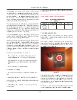
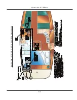
7.3.5 Bilge Pump Systems
Your boat is equipped with 1 main bilge pump and
1 (Optional) emergency bilge pump. For locations
of the bilge pump systems, consult your Mechanical
Arrangement Drawing or the Sanitary Systems Drawing.
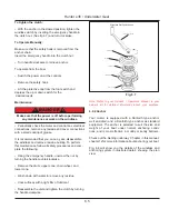
The Bilge Pump System consists of a pump and a float
switch. When the water level rises far enough to activate
the float switch, this activates the pump which lowers the
water level down to a point that the float switch stops the
power. Fig. 7.4 shows you the typical wiring.
For more information about your bilge pump system, see
Sanitary Systems.
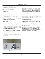
7.3.2 To manually operate your bilge pumps:
Note: The power to the MDP does not need to be energized in
order to manually operate your bilge pumps.
1. Locate the bilge pump switches at the Nav station and
switch them to the manual position.
2. Another procedure to be used in extreme circumstanc-
es involves locating the float switch and manually rotating
the float handle on the side of the float switch to simulate
the float switch being underwater. This will energize the
pump and the pump will operate.
Figure 7.4
7.3.6 Shower Sump
The shower sump is part of the Sanitary System and
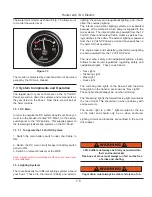
Battery Switch Panel
Main Distribution Panel
BATTERY TEST
PORT
STBD
DC DISTRIBUTION PANEL
12 VOLT D.C.
24V DC
12V DC
DC AMPS
START-STOP/PRIME
STATUS
Summary of Contents for e36
Page 1: ...V2 062012 Operator s Manual e 36 ...
Page 2: ......
Page 9: ...V2 062012 Introduction e 36 Chapter 1 ...
Page 14: ...Hunter e36 Introduction 1 6 Notes ...
Page 15: ...Documents Forms e 36 Chapter 2 and V2 062012 ...
Page 26: ...Hunter e36 Documents and Forms Maintenance Log Date Maintenance Performed Hourmeter 2 12 ...
Page 27: ...Hunter e36 Documents and Forms 2 13 Date Maintenance Performed Hourmeter Maintenance Log ...
Page 33: ...Hunter e36 Documents and Forms 2 19 Spare Parts List ...
Page 34: ...Hunter e36 Documents and Forms Dates of practice drills and onboard safety inspections 2 20 ...
Page 35: ...Hunter e36 Documents and Forms 2 21 My personal preferences for maintenance items safety gear ...
Page 36: ...Hunter e36 Documents and Forms Notes 2 22 ...
Page 37: ...V2 062012 Limited Warranty e 36 Chapter 3 ...
Page 38: ...This Page Intentionally Left Blank Hunter Limited Warranty 3 2 ...
Page 47: ...Boating Safety e 36 Chapter 4 V2 062012 ...
Page 65: ...Deck Hardware Hunter e36 Boating Safety 4 19 ...
Page 67: ...Hunter e36 Boating Safety 4 21 Notes ...
Page 68: ...Hunter e36 Boating Safety 4 22 Notes ...
Page 69: ...V2 062012 Fuel Systems e 36 Chapter 5 ...
Page 75: ...Fig 5 7 A Quick Fuel Filter Reference Hunter e36 Fuel Systems 5 7 ...
Page 82: ...Notes Hunter e36 Fuel Systems 5 14 ...
Page 83: ...V2 062012 Underwater Gear e 36 Chapter 6 ...
Page 92: ...Hunter e36 Underwater Gear 6 10 Notes ...
Page 93: ...V2 062012 DC Electric Systems e 36 Chapter 7 ...
Page 103: ...Hunter e36 DC Electric 7 11 7 8 BASIC DC POWER SUPPLY SYSTEM DIAGRAM ...
Page 104: ...Hunter e36 DC Electric 7 12 Notes ...
Page 106: ...Hunter e36 DC Electric 7 14 Notes ...
Page 107: ...V2 062012 AC Electric Systems e 36 Chapter 8 ...
Page 115: ...Hunter e36 AC Electric Systems 8 9 7 8 AC DC Electric Power Supply Diagram ...
Page 116: ...Hunter e36 AC Electric Systems 8 10 This Page Intentionally Left Blank ...
Page 117: ...Hunter e36 AC Electric Systems 8 11 Notes ...
Page 118: ...Hunter e36 AC Electric Systems 8 12 Notes ...
Page 119: ...V2 062012 Water Systems e 36 Chapter 9 ...
Page 126: ...Hunter e36 Water Systems 9 8 This Page Intentionally Left Blank ...
Page 128: ...Hunter e36 Water Systems 9 10 This Page Intentionally Left Blank ...
Page 129: ...Hunter e36 Water Systems 9 11 Notes ...
Page 130: ...Hunter e36 Water Systems 9 12 Notes ...
Page 131: ...V2 062012 Waste Systems e 36 Chapter 10 ...
Page 137: ...Hunter e36 Waste and Sanitation Systems 10 7 ...
Page 140: ...This Page Intentionally Left Blank Hunter e36 Waste and Sanitation Systems 10 10 ...
Page 141: ...Sump Pump Layout Grey Water Hunter e36 Waste and Sanitation Systems 10 11 ...
Page 142: ...This Page Intentionally Left Blank Hunter e36 Waste and Sanitation Systems 10 12 ...
Page 144: ...Hunter e36 Waste and Sanitation Systems 10 14 Notes ...
Page 145: ...V2 062012 Engines Transmissions e 36 Chapter 11 and ...
Page 154: ...Hunter e36 Engines and Transmissions 11 10 This Page Intentional Left Blank ...
Page 155: ...V2 062012 Sails Rigging e 36 Chapter 12 and ...
Page 162: ...Hunter e36 Sails and Rigging 12 8 Standing Rigging Details Standard ...
Page 163: ...Hunter e36 Sails and Rigging 12 9 Standing Rigging Details Furling ...
Page 164: ...Hunter e36 Sails and Rigging 12 10 Mast Upper Spreader Tip Details H A B C D E F G ...
Page 165: ...Hunter e36 Sails and Rigging 12 11 C A B D E F G H J K I Mast Lower Spreader Tip Details ...
Page 166: ...Hunter e36 Sails and Rigging 12 12 Standing Rigging Details ...
Page 170: ...Hunter e36 Sails and Rigging 12 16 Typical Boom Reefing Layout ...
Page 171: ...Hunter e36 Sails and Rigging 12 17 Rope Vang Details Standard Vang Details ...
Page 172: ...Hunter e36 Sails and Rigging 12 18 Rigid Vang Details Optional Vang Details ...
Page 175: ...Hunter e36 Sails and Rigging 12 21 JIB LINE TIES OFF ON CLEAT Jib Furling Line Layout ...
Page 176: ...Hunter e36 Sails and Rigging 12 22 Bridle Configuration ...
Page 179: ...Hunter e36 Sails and Rigging 12 25 Optional Spinnaker Layout ...
Page 180: ...Hunter e36 Sails and Rigging 12 26 Notes ...
Page 181: ...V2 062012 Getting Underway e 36 Chapter 13 ...
Page 188: ...Hunter e36 Getting Underway 13 8 Notes ...
Page 189: ...V2 062012 Maintenance e 36 Chapter 14 ...
Page 202: ...Notes Hunter e36 Maintenance 14 14 ...
Page 203: ...Exterior Lifting Points Hunter e36 Maintenance 14 15 ...
Page 204: ...Hunter e36 Maintenance 14 16 This Page Intentionally Left Blank ...