


Hunter e36 • Sails and Rigging
12.4
— the lazy sheet — should also be attached to the clew
of the spinnaker , led forward
in front of the headstay
,
and then back on the other side of the boat — outside
the shrouds and lifelines — to another turning block
positioned just forward of the stern pulpit. Then take that
sheet and lead it to a winch, with the slack in the sheet.
Now you are ready to hoist the spinnaker. Start by
heading off to a square run. Leave the mainsail fully
out during the hoisting procedure as it will blanket
the spinnaker and keep it from filling until you are
ready for it to be set. A good place to raise the sail
is from the leeward side, just ahead of the boom.
Once it is fully hoisted, slowly head up to your desired
course and pull in the sheet until the sail sets. Make
sure you have at least two turns of the sheet around the
winch.
Now you are off and sailing with your cruising spinnaker.
12.9 The Arch
As is customary on Hunters, the traveler is overhead, on
a stainless-steel arch, to keep the cockpit clear of the
obstruction and the boom clear of your head. The helms-
man can easily adjust the mainsheet traveler and the jib
sheets, although the mainsheet itself is at the companion-
way as illustrated above. The setup allows short handed
sailing when there are only a couple of people in the
cockpit or with an autopilot doing the steering.
12.10 B&R Rig
The B&R rig, utilized on the Hunter, eliminates the need
for a backstay to allow for a more efficient mainsail shape.
Fixed backstays are commonly being designed out of
today’s performance-oriented boats to allow the mainsail
to incorporate a full roach design - a more aerodynamic
shape both for racing and cruising performance.
To accomplish this, the B&R rig has 30 degree swept
spreaders, creating 120 degrees between each rigging
point. This tri-pod arrangement has excellent strength
for sailboat rigs, and has been used for years to support
huge radio towers.
Additional support is given to the B&R rig (and is unique
to it) with the addition of reverse diagonal rigging. For
example, the diagonals that you see beginning by the
top of the mast strut, ending at the tip of the spreader,
supports and stabilizes the upper section of the mast as
it creates a triangle with the upper shroud.
The B&R rig is designed to be pre-bent to further add
rigidity to the mast section and eliminate the need for
adjustable rigging (like backstay adjusters). This design
should prove more reliable than a rig with adjustable
backstays or runners, as there is less chance for error.
The large main, small jib, sail plan also eliminates the
need for large overlapping headsails (genoas), as the
driving power comes from the much improved shape and
size of the mainsail. This offers an easier tacking small
jib, creating good performance and more comfortable
sailing as it is less work for the crew.
As the large main is creating additional mainsheet and
leach loading, Hunter has included a cockpit arch whereby
the mainsheet and leech loads are directed to the strong
part of the boom (the out-board end) and is located at the
heaviest loading point of the mainsail. The cockpit arch
serves additional safety and comfort functions as hand-
holds and cockpit canvas attachment points.
B&R rigs have been used on thousands of sailboats, and
we are proud to incorporate this successful design on
your new Hunter.
12.11 Tuning the B&R Rig
(The information below is Hunter Marine’s opinion and
should not be considered complete or exact list of rec-
ommendations. Refer to OEM manual for more details)
The easiest method for tuning the B&R rig is to perform
step one as follows before the mast is stepped, with it
lying aft side down on two sawhorses. Begin with all rig-
ging slack. If the mast is already stepped, loosen all the
rigging, and then proceed to step one.
Start with all the rigging slack. Then induce the mast
bend by tightening the reverse diagonals (diamonds).
Measure the bend by tensioning a line or the main hal-
yard between the masthead and the gooseneck. The
maximum amount of bend should be no more than
8” [203mm] for the standard rig and no more than 2”
[50mm] for the furling mast. Measured perpendicular
from the aft face of the mast to the halyard at the deep-
est part of the bend. It can be less than that based
on the sail shape and your own preference. The bend
should also be evenly distributed along the mast to give
a smooth shape. Keep in mind that bending a furling
mast may make it more difficult to furl and will not do
much to flatten the sail as in a standard rig. It is very
important that the mast also be straight from side to side
1.
Summary of Contents for e36
Page 1: ...V2 062012 Operator s Manual e 36 ...
Page 2: ......
Page 9: ...V2 062012 Introduction e 36 Chapter 1 ...
Page 14: ...Hunter e36 Introduction 1 6 Notes ...
Page 15: ...Documents Forms e 36 Chapter 2 and V2 062012 ...
Page 26: ...Hunter e36 Documents and Forms Maintenance Log Date Maintenance Performed Hourmeter 2 12 ...
Page 27: ...Hunter e36 Documents and Forms 2 13 Date Maintenance Performed Hourmeter Maintenance Log ...
Page 33: ...Hunter e36 Documents and Forms 2 19 Spare Parts List ...
Page 34: ...Hunter e36 Documents and Forms Dates of practice drills and onboard safety inspections 2 20 ...
Page 35: ...Hunter e36 Documents and Forms 2 21 My personal preferences for maintenance items safety gear ...
Page 36: ...Hunter e36 Documents and Forms Notes 2 22 ...
Page 37: ...V2 062012 Limited Warranty e 36 Chapter 3 ...
Page 38: ...This Page Intentionally Left Blank Hunter Limited Warranty 3 2 ...
Page 47: ...Boating Safety e 36 Chapter 4 V2 062012 ...
Page 65: ...Deck Hardware Hunter e36 Boating Safety 4 19 ...
Page 67: ...Hunter e36 Boating Safety 4 21 Notes ...
Page 68: ...Hunter e36 Boating Safety 4 22 Notes ...
Page 69: ...V2 062012 Fuel Systems e 36 Chapter 5 ...
Page 75: ...Fig 5 7 A Quick Fuel Filter Reference Hunter e36 Fuel Systems 5 7 ...
Page 82: ...Notes Hunter e36 Fuel Systems 5 14 ...
Page 83: ...V2 062012 Underwater Gear e 36 Chapter 6 ...
Page 92: ...Hunter e36 Underwater Gear 6 10 Notes ...
Page 93: ...V2 062012 DC Electric Systems e 36 Chapter 7 ...
Page 103: ...Hunter e36 DC Electric 7 11 7 8 BASIC DC POWER SUPPLY SYSTEM DIAGRAM ...
Page 104: ...Hunter e36 DC Electric 7 12 Notes ...
Page 106: ...Hunter e36 DC Electric 7 14 Notes ...
Page 107: ...V2 062012 AC Electric Systems e 36 Chapter 8 ...
Page 115: ...Hunter e36 AC Electric Systems 8 9 7 8 AC DC Electric Power Supply Diagram ...
Page 116: ...Hunter e36 AC Electric Systems 8 10 This Page Intentionally Left Blank ...
Page 117: ...Hunter e36 AC Electric Systems 8 11 Notes ...
Page 118: ...Hunter e36 AC Electric Systems 8 12 Notes ...
Page 119: ...V2 062012 Water Systems e 36 Chapter 9 ...
Page 126: ...Hunter e36 Water Systems 9 8 This Page Intentionally Left Blank ...
Page 128: ...Hunter e36 Water Systems 9 10 This Page Intentionally Left Blank ...
Page 129: ...Hunter e36 Water Systems 9 11 Notes ...
Page 130: ...Hunter e36 Water Systems 9 12 Notes ...
Page 131: ...V2 062012 Waste Systems e 36 Chapter 10 ...
Page 137: ...Hunter e36 Waste and Sanitation Systems 10 7 ...
Page 140: ...This Page Intentionally Left Blank Hunter e36 Waste and Sanitation Systems 10 10 ...
Page 141: ...Sump Pump Layout Grey Water Hunter e36 Waste and Sanitation Systems 10 11 ...
Page 142: ...This Page Intentionally Left Blank Hunter e36 Waste and Sanitation Systems 10 12 ...
Page 144: ...Hunter e36 Waste and Sanitation Systems 10 14 Notes ...
Page 145: ...V2 062012 Engines Transmissions e 36 Chapter 11 and ...
Page 154: ...Hunter e36 Engines and Transmissions 11 10 This Page Intentional Left Blank ...
Page 155: ...V2 062012 Sails Rigging e 36 Chapter 12 and ...
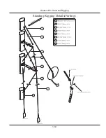
Page 162: ...Hunter e36 Sails and Rigging 12 8 Standing Rigging Details Standard ...
Page 163: ...Hunter e36 Sails and Rigging 12 9 Standing Rigging Details Furling ...
Page 164: ...Hunter e36 Sails and Rigging 12 10 Mast Upper Spreader Tip Details H A B C D E F G ...
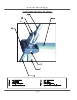
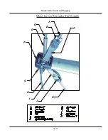
Page 165: ...Hunter e36 Sails and Rigging 12 11 C A B D E F G H J K I Mast Lower Spreader Tip Details ...
Page 166: ...Hunter e36 Sails and Rigging 12 12 Standing Rigging Details ...
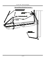
Page 170: ...Hunter e36 Sails and Rigging 12 16 Typical Boom Reefing Layout ...
Page 171: ...Hunter e36 Sails and Rigging 12 17 Rope Vang Details Standard Vang Details ...
Page 172: ...Hunter e36 Sails and Rigging 12 18 Rigid Vang Details Optional Vang Details ...
Page 175: ...Hunter e36 Sails and Rigging 12 21 JIB LINE TIES OFF ON CLEAT Jib Furling Line Layout ...
Page 176: ...Hunter e36 Sails and Rigging 12 22 Bridle Configuration ...
Page 179: ...Hunter e36 Sails and Rigging 12 25 Optional Spinnaker Layout ...
Page 180: ...Hunter e36 Sails and Rigging 12 26 Notes ...
Page 181: ...V2 062012 Getting Underway e 36 Chapter 13 ...
Page 188: ...Hunter e36 Getting Underway 13 8 Notes ...
Page 189: ...V2 062012 Maintenance e 36 Chapter 14 ...
Page 202: ...Notes Hunter e36 Maintenance 14 14 ...
Page 203: ...Exterior Lifting Points Hunter e36 Maintenance 14 15 ...
Page 204: ...Hunter e36 Maintenance 14 16 This Page Intentionally Left Blank ...