


Hunter e36 • Water Systems
9.2
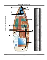
The fresh and raw water systems consist of the following
components:
Dockside Water Supply
Fresh Water Tanks and Fills
Fresh Water Pump
A/C Cooling Pump
Raw Water Pick-up and Strainer
A/C Pick-up and Strainer
Generator Cooling Pick-up and Strainer
Engine Seacocks and Strainers
Fixtures and Valves
Water Heater
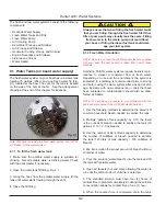
9.1 Water Tanks (on board water supply)
The fresh water system on your boat has one water tank
totaling 75 gallons (284L) and one fresh water fill (Fig.
9.1) located at the bow. The vent for the tank is located
on the side of the hull, at the fill. See the arrangement
drawing at the end of this chapter for locations.
Note: Whenever servicing the fresh water pumps, shut off the
DC breaker for the water system.
9.1.1 To fill the fresh water tank:
1. Make sure the potable water supply is suitable for
drinking. Not all potable water is drinking water. Check
with the dockmaster if necessary.
2. Open the water tank fill fitting. Fig. 9.1
3. Using the hose from the potable water supply, fill the
tank until water starts flowing through the vent.
4. Close the fill fitting.
•
•
•
•
•
•
•
•
•
•
CAUTION
!
!
Always ensure that when filling the fresh water tanks
that you are filling through the fresh water fill. Other
fills or pump outs may visually look the same. Filling
fresh water in to the waste pump out could flood
your boat, or filling the diesel fuel tank could dam-
age your fuel system.
9.1.2 Fresh Water Sanitation
NOTE: Be sure and read the OEM manuals that are supplied
with your boat, the next section is taken from one of those
manuals.
Sanitizing Potable water systems require periodic main-
tenance to deliver a consistent flow of fresh water.
Depending on use and the environment the system is
subjected to, sanitizing is recommended prior to storing
and before using the water system after a period of stor-
age. Systems with new components, or ones that have
been subjected to contamination, should also be disin-
fected as follows:
NOTE: The sanitizing procedure is in conformance with the
approved procedures of the US Public Health Service.)
1. Use the following methods to determine the amount of
common household bleach needed to sanitize the tank:
A. Multiply “gallons of tank capacity” by 0.13; the result
is the ounces of bleach needed to sanitize the tank (30
gallons X .13 = 3.9 oz bleach).
B. Use the number of liters of tank capacity to determine
the number of milliliters of bleach needed to sanitize
the tank (120 liters of tank capacity = 120 milliliters of
bleach).
2. Mix into solution the proper amount of bleach within a
container of water
3. Pour the solution (water/bleach) into the tank and fill
the tank with potable water.
4. Open all faucets (hot and cold) allowing the water to
run until the distinct odor of chlorine is detected.
5. The standard solution must have four (4) hours of
contact time to disinfect completely. Doubling the solution
concentration allows for contact time of one (1) hour.
6. When the contact time is completed, drain the tank.
Fig. 9.1
Summary of Contents for e36
Page 1: ...V2 062012 Operator s Manual e 36 ...
Page 2: ......
Page 9: ...V2 062012 Introduction e 36 Chapter 1 ...
Page 14: ...Hunter e36 Introduction 1 6 Notes ...
Page 15: ...Documents Forms e 36 Chapter 2 and V2 062012 ...
Page 26: ...Hunter e36 Documents and Forms Maintenance Log Date Maintenance Performed Hourmeter 2 12 ...
Page 27: ...Hunter e36 Documents and Forms 2 13 Date Maintenance Performed Hourmeter Maintenance Log ...
Page 33: ...Hunter e36 Documents and Forms 2 19 Spare Parts List ...
Page 34: ...Hunter e36 Documents and Forms Dates of practice drills and onboard safety inspections 2 20 ...
Page 35: ...Hunter e36 Documents and Forms 2 21 My personal preferences for maintenance items safety gear ...
Page 36: ...Hunter e36 Documents and Forms Notes 2 22 ...
Page 37: ...V2 062012 Limited Warranty e 36 Chapter 3 ...
Page 38: ...This Page Intentionally Left Blank Hunter Limited Warranty 3 2 ...
Page 47: ...Boating Safety e 36 Chapter 4 V2 062012 ...
Page 65: ...Deck Hardware Hunter e36 Boating Safety 4 19 ...
Page 67: ...Hunter e36 Boating Safety 4 21 Notes ...
Page 68: ...Hunter e36 Boating Safety 4 22 Notes ...
Page 69: ...V2 062012 Fuel Systems e 36 Chapter 5 ...
Page 75: ...Fig 5 7 A Quick Fuel Filter Reference Hunter e36 Fuel Systems 5 7 ...
Page 82: ...Notes Hunter e36 Fuel Systems 5 14 ...
Page 83: ...V2 062012 Underwater Gear e 36 Chapter 6 ...
Page 92: ...Hunter e36 Underwater Gear 6 10 Notes ...
Page 93: ...V2 062012 DC Electric Systems e 36 Chapter 7 ...
Page 103: ...Hunter e36 DC Electric 7 11 7 8 BASIC DC POWER SUPPLY SYSTEM DIAGRAM ...
Page 104: ...Hunter e36 DC Electric 7 12 Notes ...
Page 106: ...Hunter e36 DC Electric 7 14 Notes ...
Page 107: ...V2 062012 AC Electric Systems e 36 Chapter 8 ...
Page 115: ...Hunter e36 AC Electric Systems 8 9 7 8 AC DC Electric Power Supply Diagram ...
Page 116: ...Hunter e36 AC Electric Systems 8 10 This Page Intentionally Left Blank ...
Page 117: ...Hunter e36 AC Electric Systems 8 11 Notes ...
Page 118: ...Hunter e36 AC Electric Systems 8 12 Notes ...
Page 119: ...V2 062012 Water Systems e 36 Chapter 9 ...
Page 126: ...Hunter e36 Water Systems 9 8 This Page Intentionally Left Blank ...
Page 128: ...Hunter e36 Water Systems 9 10 This Page Intentionally Left Blank ...
Page 129: ...Hunter e36 Water Systems 9 11 Notes ...
Page 130: ...Hunter e36 Water Systems 9 12 Notes ...
Page 131: ...V2 062012 Waste Systems e 36 Chapter 10 ...
Page 137: ...Hunter e36 Waste and Sanitation Systems 10 7 ...
Page 140: ...This Page Intentionally Left Blank Hunter e36 Waste and Sanitation Systems 10 10 ...
Page 141: ...Sump Pump Layout Grey Water Hunter e36 Waste and Sanitation Systems 10 11 ...
Page 142: ...This Page Intentionally Left Blank Hunter e36 Waste and Sanitation Systems 10 12 ...
Page 144: ...Hunter e36 Waste and Sanitation Systems 10 14 Notes ...
Page 145: ...V2 062012 Engines Transmissions e 36 Chapter 11 and ...
Page 154: ...Hunter e36 Engines and Transmissions 11 10 This Page Intentional Left Blank ...
Page 155: ...V2 062012 Sails Rigging e 36 Chapter 12 and ...
Page 162: ...Hunter e36 Sails and Rigging 12 8 Standing Rigging Details Standard ...
Page 163: ...Hunter e36 Sails and Rigging 12 9 Standing Rigging Details Furling ...
Page 164: ...Hunter e36 Sails and Rigging 12 10 Mast Upper Spreader Tip Details H A B C D E F G ...
Page 165: ...Hunter e36 Sails and Rigging 12 11 C A B D E F G H J K I Mast Lower Spreader Tip Details ...
Page 166: ...Hunter e36 Sails and Rigging 12 12 Standing Rigging Details ...
Page 170: ...Hunter e36 Sails and Rigging 12 16 Typical Boom Reefing Layout ...
Page 171: ...Hunter e36 Sails and Rigging 12 17 Rope Vang Details Standard Vang Details ...
Page 172: ...Hunter e36 Sails and Rigging 12 18 Rigid Vang Details Optional Vang Details ...
Page 175: ...Hunter e36 Sails and Rigging 12 21 JIB LINE TIES OFF ON CLEAT Jib Furling Line Layout ...
Page 176: ...Hunter e36 Sails and Rigging 12 22 Bridle Configuration ...
Page 179: ...Hunter e36 Sails and Rigging 12 25 Optional Spinnaker Layout ...
Page 180: ...Hunter e36 Sails and Rigging 12 26 Notes ...
Page 181: ...V2 062012 Getting Underway e 36 Chapter 13 ...
Page 188: ...Hunter e36 Getting Underway 13 8 Notes ...
Page 189: ...V2 062012 Maintenance e 36 Chapter 14 ...
Page 202: ...Notes Hunter e36 Maintenance 14 14 ...
Page 203: ...Exterior Lifting Points Hunter e36 Maintenance 14 15 ...
Page 204: ...Hunter e36 Maintenance 14 16 This Page Intentionally Left Blank ...