


Hunter e36 • Boating Safety
4.10
For minimum protection, CO alarms should be
installed near all sleeping areas.
For maximum protection, CO alarms should be
installed in all sleeping areas.
Where not to Install Alarms:
Not behind furniture, drapes, closets, or areas that will
block air flow to the alarm.
Not within 12 inches of window openings, exterior
doors, heating or return air vents, or any other drafty
areas.
The alarm should not be located within 5 (1.5 m) feet
of any cooking appliance.
For information on taking care of your CO alarm, see
the Maintenance chapter of this manual.
Limitations of the CO alarm:
Carbon Monoxide alarms will not work without power.
Some examples causing no alarm power are: A blown
or missing fuse, broken wire, faulty connection, circuit
breaker tripped, or a discharged battery.
This alarm will only detect the presence of CO gas at the
sensor. Carbon Monoxide gas may be present in other
areas.
Carbon Monoxide alarms may not be heard. The alarm
loudness is designed to meet or exceed the regula-
tory standards. However, the alarm may not be heard if
alarms are located in remote locations or behind closed
doors. The alarm may not be heard by persons who are
hard of hearing, have consumed alcoholic beverages,
taken prescription or non-prescription medication, or
illegal drugs.
This alarm is designed to detect Carbon Monoxide from
any source of combustion. It is not designed to detect
smoke, fire, or any other gasses. The alarm may not
sound at low Carbon Monoxide levels. This product is
intended for use in ordinary indoor locations of living
spaces. It is not designed to measure compliance with
Occupational Safety Health Administration (OSHA) com-
mercial or industrial standards. Individuals with medical
problems may consider using warning devices which pro-
vide audible and visual signals for levels under 30 PPM.
•
•
•
•
•
•
•
How else to protect your family from Carbon Monoxide:
Ensure alarms are installed properly. Carefully read and
follow ALL the instructions in this manual. Test your unit
every week. Alarms that do not work, do not alert you to
the presence of Carbon Monoxide.
Make regular visual inspections of all fuel burning equip-
ment including gas water heaters, kitchen gas stoves,
space heaters, gas dryers, or other pilots. Check the
color of the flame! The color should be blue.
Make regular visual inspections of the engine and gen-
erator exhaust systems. Cracked exhaust systems can
allow Carbon Monoxide to enter the living area.
Professionally maintain your engine and generator.
Although all gas engines and generators produce Carbon
Monoxide, a poorly tuned engine and generator will pro-
duce greater amounts of Carbon Monoxide.
4.3 Other Dangers
4.3.1 Weather
Storms rarely appear without advanced notice. Check
the weather forecast before you begin a day of boating.
Be aware, however, that weather conditions can change
rapidly. If you have a marine radio, listen to the weather
reports issued by the U.S. Coast Guard and others. If you
have a portable radio, keep it tuned to a station broad-
casting frequent weather reports. Many boating clubs fly
weather signals. Learn to recognize these signals and
listen to your local forecasts before leaving port.
Your surroundings can also be a good indicator of chang-
ing weather conditions. Watch for changes in wind direc-
tion or cloud formations. There is no substitute for a good
understanding of weather conditions and what to do
when the weather takes a turn for the worse.
Page 4.15 will explain the dangers of Lightning strikes,
with an overview of your protection area.
Refer to the Chapman's Manual for instructions and
precautions in operating a craft in heavy weather.
4.3.2 Fog
You can judge the likelihood of fog formation by peri-
odically measuring the air temperature and the dew point
temperature. If the difference between these two tem-
peratures is small, fog is likely to develop.
•
Summary of Contents for e36
Page 1: ...V2 062012 Operator s Manual e 36 ...
Page 2: ......
Page 9: ...V2 062012 Introduction e 36 Chapter 1 ...
Page 14: ...Hunter e36 Introduction 1 6 Notes ...
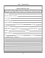
Page 15: ...Documents Forms e 36 Chapter 2 and V2 062012 ...
Page 26: ...Hunter e36 Documents and Forms Maintenance Log Date Maintenance Performed Hourmeter 2 12 ...
Page 27: ...Hunter e36 Documents and Forms 2 13 Date Maintenance Performed Hourmeter Maintenance Log ...
Page 33: ...Hunter e36 Documents and Forms 2 19 Spare Parts List ...
Page 34: ...Hunter e36 Documents and Forms Dates of practice drills and onboard safety inspections 2 20 ...
Page 35: ...Hunter e36 Documents and Forms 2 21 My personal preferences for maintenance items safety gear ...
Page 36: ...Hunter e36 Documents and Forms Notes 2 22 ...
Page 37: ...V2 062012 Limited Warranty e 36 Chapter 3 ...
Page 38: ...This Page Intentionally Left Blank Hunter Limited Warranty 3 2 ...
Page 47: ...Boating Safety e 36 Chapter 4 V2 062012 ...
Page 65: ...Deck Hardware Hunter e36 Boating Safety 4 19 ...
Page 67: ...Hunter e36 Boating Safety 4 21 Notes ...
Page 68: ...Hunter e36 Boating Safety 4 22 Notes ...
Page 69: ...V2 062012 Fuel Systems e 36 Chapter 5 ...
Page 75: ...Fig 5 7 A Quick Fuel Filter Reference Hunter e36 Fuel Systems 5 7 ...
Page 82: ...Notes Hunter e36 Fuel Systems 5 14 ...
Page 83: ...V2 062012 Underwater Gear e 36 Chapter 6 ...
Page 92: ...Hunter e36 Underwater Gear 6 10 Notes ...
Page 93: ...V2 062012 DC Electric Systems e 36 Chapter 7 ...
Page 103: ...Hunter e36 DC Electric 7 11 7 8 BASIC DC POWER SUPPLY SYSTEM DIAGRAM ...
Page 104: ...Hunter e36 DC Electric 7 12 Notes ...
Page 106: ...Hunter e36 DC Electric 7 14 Notes ...
Page 107: ...V2 062012 AC Electric Systems e 36 Chapter 8 ...
Page 115: ...Hunter e36 AC Electric Systems 8 9 7 8 AC DC Electric Power Supply Diagram ...
Page 116: ...Hunter e36 AC Electric Systems 8 10 This Page Intentionally Left Blank ...
Page 117: ...Hunter e36 AC Electric Systems 8 11 Notes ...
Page 118: ...Hunter e36 AC Electric Systems 8 12 Notes ...
Page 119: ...V2 062012 Water Systems e 36 Chapter 9 ...
Page 126: ...Hunter e36 Water Systems 9 8 This Page Intentionally Left Blank ...
Page 128: ...Hunter e36 Water Systems 9 10 This Page Intentionally Left Blank ...
Page 129: ...Hunter e36 Water Systems 9 11 Notes ...
Page 130: ...Hunter e36 Water Systems 9 12 Notes ...
Page 131: ...V2 062012 Waste Systems e 36 Chapter 10 ...
Page 137: ...Hunter e36 Waste and Sanitation Systems 10 7 ...
Page 140: ...This Page Intentionally Left Blank Hunter e36 Waste and Sanitation Systems 10 10 ...
Page 141: ...Sump Pump Layout Grey Water Hunter e36 Waste and Sanitation Systems 10 11 ...
Page 142: ...This Page Intentionally Left Blank Hunter e36 Waste and Sanitation Systems 10 12 ...
Page 144: ...Hunter e36 Waste and Sanitation Systems 10 14 Notes ...
Page 145: ...V2 062012 Engines Transmissions e 36 Chapter 11 and ...
Page 154: ...Hunter e36 Engines and Transmissions 11 10 This Page Intentional Left Blank ...
Page 155: ...V2 062012 Sails Rigging e 36 Chapter 12 and ...
Page 162: ...Hunter e36 Sails and Rigging 12 8 Standing Rigging Details Standard ...
Page 163: ...Hunter e36 Sails and Rigging 12 9 Standing Rigging Details Furling ...
Page 164: ...Hunter e36 Sails and Rigging 12 10 Mast Upper Spreader Tip Details H A B C D E F G ...
Page 165: ...Hunter e36 Sails and Rigging 12 11 C A B D E F G H J K I Mast Lower Spreader Tip Details ...
Page 166: ...Hunter e36 Sails and Rigging 12 12 Standing Rigging Details ...
Page 170: ...Hunter e36 Sails and Rigging 12 16 Typical Boom Reefing Layout ...
Page 171: ...Hunter e36 Sails and Rigging 12 17 Rope Vang Details Standard Vang Details ...
Page 172: ...Hunter e36 Sails and Rigging 12 18 Rigid Vang Details Optional Vang Details ...
Page 175: ...Hunter e36 Sails and Rigging 12 21 JIB LINE TIES OFF ON CLEAT Jib Furling Line Layout ...
Page 176: ...Hunter e36 Sails and Rigging 12 22 Bridle Configuration ...
Page 179: ...Hunter e36 Sails and Rigging 12 25 Optional Spinnaker Layout ...
Page 180: ...Hunter e36 Sails and Rigging 12 26 Notes ...
Page 181: ...V2 062012 Getting Underway e 36 Chapter 13 ...
Page 188: ...Hunter e36 Getting Underway 13 8 Notes ...
Page 189: ...V2 062012 Maintenance e 36 Chapter 14 ...
Page 202: ...Notes Hunter e36 Maintenance 14 14 ...
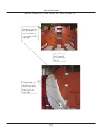
Page 203: ...Exterior Lifting Points Hunter e36 Maintenance 14 15 ...
Page 204: ...Hunter e36 Maintenance 14 16 This Page Intentionally Left Blank ...