


Hunter e36 • Maintenance
14.8
tion.
* Realign propeller shaft
* Tighten all engine mounts.
* Complete engine maintenance as recommended by
engine manufacturer.
* Tighten all hose clamps and lubricate them.
* Check and tighten all pressurized water system fit-
tings.
* Check and service batteries, tighten battery connec-
tions, and lubricate as needed.
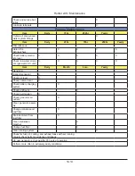
At the end of this chapter, you will find a maintenance
schedule. It is important that you keep the manufactur-
er’s documentation for the components and follow the
maintenance schedules and procedures listed in that
literature. This information takes precedence over what
is supplied by the boat manufacturer.
14.6 Storage and Lifting
In most cases, the reason for storage is winter layup.
The information in this section is a general guide. Your
boat dealer or a competent boatyard should prepare your
boat for winter storage. If you are removing your boat
from the water for another reason, use the information in
this section as a guideline. Following the procedures in
this section helps to extend the life of your boat and its
equipment and simplifies re-commencing in the spring.
Indoor storage is beneficial if you are storing your boat in
a climate that produces ice and snow. However, the stor-
age building should be adequately ventilated, not tightly
closed. Ventilation, both around and throughout the boat,
is very important.
If you use outdoor storage facilities, cover your boat with
a canvas cover with provisions for ventilation to keep the
boat from “sweating.” Building a frame over the boat to
support the canvas will allow the passage of air around
the boat. The frame should be a few inches wider than
the boat so the canvas will clear the rails.
Before preparing your boat for winter storage, check the
condition of the boat and its systems and equipment.
Note any repairs needed. The need for other repairs may
become apparent during winterization. Make arrange-
ments to have the repairs completed.
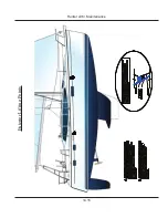
14.6.1 Lifting Your Boat
Following are guidelines which will help prevent damage
to your boat as it is being lifted.
* Never hoist the boat with a greater than normal accu-
mulation of water in the bilge. Fuel and water tanks
should be empty.
* Place slings where indicated by the sling tags on the
gunwale. Proper location of the aft sling is critical. Lifting
aft of the station indicated may damage the propeller
shaft. Lifting forward of the station indicated, with the
sling under the exhaust outlets, may cause cracking
which is not covered by the warranty. Blocks or pads at
the chine corners will help keep pressure to a minimum
at this point.
* Disconnect the propeller shafts at the transmissions to
prevent damage to the transmission.
* Use flat, wide slings made of belting and spreader bars
long enough to keep pressure off the gunwale. Do not
use cable slings. Pressure by the slings on the gunwale
can cause severe gelcoat crazing or more serious hull
damage.
* The spreader bar at each sling should be as long as the
distance across the widest point the sling surrounds.
* Weight should be primarily distributed along the keel.
If a marine railway or platform is used, locate and adjust
the blocking to distribute the weight over several areas at
the intersection of stringers and bulkheads. The bunks
and/or blocks should match deadrise angle and provide
adequate support and stability.
* When lifting the boat, keep the bow higher than the
stern so the exhaust lines can drain. This will keep water
from running forward through the manifold and into the
engine itself where the water can become trapped.
Note: Keep the bow higher than the stern every time the boat
is lifted. Do not lift the stern to change a propeller. Doing so
can cause water to enter the engine. Engine failure is possible
if water enters the engine cylinders. This water can cause
hydrolock and bend the piston rods. Even a small amount of
water can cause rust or other damage.
14.6.3 Draining Your Boat
Your boat has bilge pumps for draining water from the
bilges. Some compartments in the bilge may not drain
completely because of the position of the boat. Pump
Summary of Contents for e36
Page 1: ...V2 062012 Operator s Manual e 36 ...
Page 2: ......
Page 9: ...V2 062012 Introduction e 36 Chapter 1 ...
Page 14: ...Hunter e36 Introduction 1 6 Notes ...
Page 15: ...Documents Forms e 36 Chapter 2 and V2 062012 ...
Page 26: ...Hunter e36 Documents and Forms Maintenance Log Date Maintenance Performed Hourmeter 2 12 ...
Page 27: ...Hunter e36 Documents and Forms 2 13 Date Maintenance Performed Hourmeter Maintenance Log ...
Page 33: ...Hunter e36 Documents and Forms 2 19 Spare Parts List ...
Page 34: ...Hunter e36 Documents and Forms Dates of practice drills and onboard safety inspections 2 20 ...
Page 35: ...Hunter e36 Documents and Forms 2 21 My personal preferences for maintenance items safety gear ...
Page 36: ...Hunter e36 Documents and Forms Notes 2 22 ...
Page 37: ...V2 062012 Limited Warranty e 36 Chapter 3 ...
Page 38: ...This Page Intentionally Left Blank Hunter Limited Warranty 3 2 ...
Page 47: ...Boating Safety e 36 Chapter 4 V2 062012 ...
Page 65: ...Deck Hardware Hunter e36 Boating Safety 4 19 ...
Page 67: ...Hunter e36 Boating Safety 4 21 Notes ...
Page 68: ...Hunter e36 Boating Safety 4 22 Notes ...
Page 69: ...V2 062012 Fuel Systems e 36 Chapter 5 ...
Page 75: ...Fig 5 7 A Quick Fuel Filter Reference Hunter e36 Fuel Systems 5 7 ...
Page 82: ...Notes Hunter e36 Fuel Systems 5 14 ...
Page 83: ...V2 062012 Underwater Gear e 36 Chapter 6 ...
Page 92: ...Hunter e36 Underwater Gear 6 10 Notes ...
Page 93: ...V2 062012 DC Electric Systems e 36 Chapter 7 ...
Page 103: ...Hunter e36 DC Electric 7 11 7 8 BASIC DC POWER SUPPLY SYSTEM DIAGRAM ...
Page 104: ...Hunter e36 DC Electric 7 12 Notes ...
Page 106: ...Hunter e36 DC Electric 7 14 Notes ...
Page 107: ...V2 062012 AC Electric Systems e 36 Chapter 8 ...
Page 115: ...Hunter e36 AC Electric Systems 8 9 7 8 AC DC Electric Power Supply Diagram ...
Page 116: ...Hunter e36 AC Electric Systems 8 10 This Page Intentionally Left Blank ...
Page 117: ...Hunter e36 AC Electric Systems 8 11 Notes ...
Page 118: ...Hunter e36 AC Electric Systems 8 12 Notes ...
Page 119: ...V2 062012 Water Systems e 36 Chapter 9 ...
Page 126: ...Hunter e36 Water Systems 9 8 This Page Intentionally Left Blank ...
Page 128: ...Hunter e36 Water Systems 9 10 This Page Intentionally Left Blank ...
Page 129: ...Hunter e36 Water Systems 9 11 Notes ...
Page 130: ...Hunter e36 Water Systems 9 12 Notes ...
Page 131: ...V2 062012 Waste Systems e 36 Chapter 10 ...
Page 137: ...Hunter e36 Waste and Sanitation Systems 10 7 ...
Page 140: ...This Page Intentionally Left Blank Hunter e36 Waste and Sanitation Systems 10 10 ...
Page 141: ...Sump Pump Layout Grey Water Hunter e36 Waste and Sanitation Systems 10 11 ...
Page 142: ...This Page Intentionally Left Blank Hunter e36 Waste and Sanitation Systems 10 12 ...
Page 144: ...Hunter e36 Waste and Sanitation Systems 10 14 Notes ...
Page 145: ...V2 062012 Engines Transmissions e 36 Chapter 11 and ...
Page 154: ...Hunter e36 Engines and Transmissions 11 10 This Page Intentional Left Blank ...
Page 155: ...V2 062012 Sails Rigging e 36 Chapter 12 and ...
Page 162: ...Hunter e36 Sails and Rigging 12 8 Standing Rigging Details Standard ...
Page 163: ...Hunter e36 Sails and Rigging 12 9 Standing Rigging Details Furling ...
Page 164: ...Hunter e36 Sails and Rigging 12 10 Mast Upper Spreader Tip Details H A B C D E F G ...
Page 165: ...Hunter e36 Sails and Rigging 12 11 C A B D E F G H J K I Mast Lower Spreader Tip Details ...
Page 166: ...Hunter e36 Sails and Rigging 12 12 Standing Rigging Details ...
Page 170: ...Hunter e36 Sails and Rigging 12 16 Typical Boom Reefing Layout ...
Page 171: ...Hunter e36 Sails and Rigging 12 17 Rope Vang Details Standard Vang Details ...
Page 172: ...Hunter e36 Sails and Rigging 12 18 Rigid Vang Details Optional Vang Details ...
Page 175: ...Hunter e36 Sails and Rigging 12 21 JIB LINE TIES OFF ON CLEAT Jib Furling Line Layout ...
Page 176: ...Hunter e36 Sails and Rigging 12 22 Bridle Configuration ...
Page 179: ...Hunter e36 Sails and Rigging 12 25 Optional Spinnaker Layout ...
Page 180: ...Hunter e36 Sails and Rigging 12 26 Notes ...
Page 181: ...V2 062012 Getting Underway e 36 Chapter 13 ...
Page 188: ...Hunter e36 Getting Underway 13 8 Notes ...
Page 189: ...V2 062012 Maintenance e 36 Chapter 14 ...
Page 202: ...Notes Hunter e36 Maintenance 14 14 ...
Page 203: ...Exterior Lifting Points Hunter e36 Maintenance 14 15 ...
Page 204: ...Hunter e36 Maintenance 14 16 This Page Intentionally Left Blank ...