


Hunter e36 • Engines and Transmissions
11.3
Important: Engines are not warranted by Hunter Corporation,
these warranties are written by the engine manufacturers.
DANGER
!
!
When occupying the engine room, or any area that
mechanical equipment may be located, always be
aware of moving parts or components. Death or
dismemberment may be the result of being caught in
moving machinery.
Important: Engines require air to operate. For this reason, do
not operate the engine or generator with this area obstructed.
Important: The engine manual supplied by the manufac-
turer includes complete and detailed information about oper-
ating and maintaining your boat’s engines. Be sure to read
it. Do not start or operate the boat’s engines until you
have done so. The life and performance you receive from
your engines depends greatly on the way you care for it.
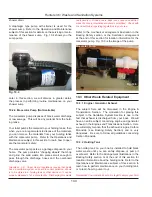
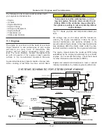
11.1.1 Engine Mounts
The engine mounts supplied with your boat are manu-
factured by the engine manufacturer. These mounts are
designed specifically for the engine in which they are
attached.
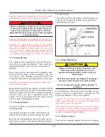
Most engine mounts are designed for adjustment side-
ways as well as vertical. Vertical adjustment nuts lock
up or down on the threaded vertical stud, with a slot
provided to allow side to side adjustment on the engine.
Important: It is advisable to spray a protective coating on the
studs to prevent corrosion.
Many factors warrant the size and type of engine mounts
that are used. These mounts also contain isolators which
isolate the engine from the boat or stringers to dampen
vibration, noise. and other undesirable effects from
engines. For more information about the engine mounts
see the engine manufacturers manuals.
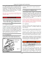
11.1.2 Engine Controls
The engine controls on your boat are located on the
steering pedestal.
The straight up position is neutral, shift forward to go
forward, moving further forward increases the speed.
Move the lever backwards for reverse, the same as for-
ward more movement in the reverse direction increases
the engine speed.
Press and hold the center button on the shift lever, and
move the lever forward to increase the engine RPM
without shifting into gear.
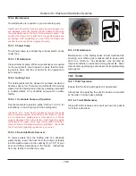
11.1.3 Engine Monitoring
CAUTION
!
!
Always monitor your boats oil pressure, and
water temp. while underway, even if your
engines are equipped with an alarm system to
monitor these.
Shut down the engines immediately if the gauges
are not in normal ranges or an alarm sounds.
Do not restart your engines until the problem is
corrected.
For information on the correct levels for engine running,
please consult your engine owner’s manuals from the
engine manufacturer in your owner’s packet.
Important: The Hour meter will run if you leave the ignition
switch on when the engine is not running. This unnecessarily
increases the number of engine hours.
Note: Instruments have a tolerance for accuracy. In addition,
each engine may operate at differing values at the same RPM.
As long as the instruments are reading within the proper operat-
ing range, the engine is operating properly.
11.1.4 Engine Cooling
There are two separate systems that cool your engines.
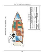
Fig. 11.1
Summary of Contents for e36
Page 1: ...V2 062012 Operator s Manual e 36 ...
Page 2: ......
Page 9: ...V2 062012 Introduction e 36 Chapter 1 ...
Page 14: ...Hunter e36 Introduction 1 6 Notes ...
Page 15: ...Documents Forms e 36 Chapter 2 and V2 062012 ...
Page 26: ...Hunter e36 Documents and Forms Maintenance Log Date Maintenance Performed Hourmeter 2 12 ...
Page 27: ...Hunter e36 Documents and Forms 2 13 Date Maintenance Performed Hourmeter Maintenance Log ...
Page 33: ...Hunter e36 Documents and Forms 2 19 Spare Parts List ...
Page 34: ...Hunter e36 Documents and Forms Dates of practice drills and onboard safety inspections 2 20 ...
Page 35: ...Hunter e36 Documents and Forms 2 21 My personal preferences for maintenance items safety gear ...
Page 36: ...Hunter e36 Documents and Forms Notes 2 22 ...
Page 37: ...V2 062012 Limited Warranty e 36 Chapter 3 ...
Page 38: ...This Page Intentionally Left Blank Hunter Limited Warranty 3 2 ...
Page 47: ...Boating Safety e 36 Chapter 4 V2 062012 ...
Page 65: ...Deck Hardware Hunter e36 Boating Safety 4 19 ...
Page 67: ...Hunter e36 Boating Safety 4 21 Notes ...
Page 68: ...Hunter e36 Boating Safety 4 22 Notes ...
Page 69: ...V2 062012 Fuel Systems e 36 Chapter 5 ...
Page 75: ...Fig 5 7 A Quick Fuel Filter Reference Hunter e36 Fuel Systems 5 7 ...
Page 82: ...Notes Hunter e36 Fuel Systems 5 14 ...
Page 83: ...V2 062012 Underwater Gear e 36 Chapter 6 ...
Page 92: ...Hunter e36 Underwater Gear 6 10 Notes ...
Page 93: ...V2 062012 DC Electric Systems e 36 Chapter 7 ...
Page 103: ...Hunter e36 DC Electric 7 11 7 8 BASIC DC POWER SUPPLY SYSTEM DIAGRAM ...
Page 104: ...Hunter e36 DC Electric 7 12 Notes ...
Page 106: ...Hunter e36 DC Electric 7 14 Notes ...
Page 107: ...V2 062012 AC Electric Systems e 36 Chapter 8 ...
Page 115: ...Hunter e36 AC Electric Systems 8 9 7 8 AC DC Electric Power Supply Diagram ...
Page 116: ...Hunter e36 AC Electric Systems 8 10 This Page Intentionally Left Blank ...
Page 117: ...Hunter e36 AC Electric Systems 8 11 Notes ...
Page 118: ...Hunter e36 AC Electric Systems 8 12 Notes ...
Page 119: ...V2 062012 Water Systems e 36 Chapter 9 ...
Page 126: ...Hunter e36 Water Systems 9 8 This Page Intentionally Left Blank ...
Page 128: ...Hunter e36 Water Systems 9 10 This Page Intentionally Left Blank ...
Page 129: ...Hunter e36 Water Systems 9 11 Notes ...
Page 130: ...Hunter e36 Water Systems 9 12 Notes ...
Page 131: ...V2 062012 Waste Systems e 36 Chapter 10 ...
Page 137: ...Hunter e36 Waste and Sanitation Systems 10 7 ...
Page 140: ...This Page Intentionally Left Blank Hunter e36 Waste and Sanitation Systems 10 10 ...
Page 141: ...Sump Pump Layout Grey Water Hunter e36 Waste and Sanitation Systems 10 11 ...
Page 142: ...This Page Intentionally Left Blank Hunter e36 Waste and Sanitation Systems 10 12 ...
Page 144: ...Hunter e36 Waste and Sanitation Systems 10 14 Notes ...
Page 145: ...V2 062012 Engines Transmissions e 36 Chapter 11 and ...
Page 154: ...Hunter e36 Engines and Transmissions 11 10 This Page Intentional Left Blank ...
Page 155: ...V2 062012 Sails Rigging e 36 Chapter 12 and ...
Page 162: ...Hunter e36 Sails and Rigging 12 8 Standing Rigging Details Standard ...
Page 163: ...Hunter e36 Sails and Rigging 12 9 Standing Rigging Details Furling ...
Page 164: ...Hunter e36 Sails and Rigging 12 10 Mast Upper Spreader Tip Details H A B C D E F G ...
Page 165: ...Hunter e36 Sails and Rigging 12 11 C A B D E F G H J K I Mast Lower Spreader Tip Details ...
Page 166: ...Hunter e36 Sails and Rigging 12 12 Standing Rigging Details ...
Page 170: ...Hunter e36 Sails and Rigging 12 16 Typical Boom Reefing Layout ...
Page 171: ...Hunter e36 Sails and Rigging 12 17 Rope Vang Details Standard Vang Details ...
Page 172: ...Hunter e36 Sails and Rigging 12 18 Rigid Vang Details Optional Vang Details ...
Page 175: ...Hunter e36 Sails and Rigging 12 21 JIB LINE TIES OFF ON CLEAT Jib Furling Line Layout ...
Page 176: ...Hunter e36 Sails and Rigging 12 22 Bridle Configuration ...
Page 179: ...Hunter e36 Sails and Rigging 12 25 Optional Spinnaker Layout ...
Page 180: ...Hunter e36 Sails and Rigging 12 26 Notes ...
Page 181: ...V2 062012 Getting Underway e 36 Chapter 13 ...
Page 188: ...Hunter e36 Getting Underway 13 8 Notes ...
Page 189: ...V2 062012 Maintenance e 36 Chapter 14 ...
Page 202: ...Notes Hunter e36 Maintenance 14 14 ...
Page 203: ...Exterior Lifting Points Hunter e36 Maintenance 14 15 ...
Page 204: ...Hunter e36 Maintenance 14 16 This Page Intentionally Left Blank ...