


Hunter e36 • Engines and Transmissions
11.2
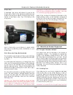
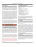
The following is a list of components associated with
your engines and transmissions.
Engine
Controls
Engine Monitoring
Engine Cooling
Emergency Equipment
Engine Exhaust
Transmission (s)
Shifters and Controls
11.1 Engines
The engine on your boat is at the heart of your boat.
Proper attention to and maintenance of your engine
will assure you many hours of pleasurable, safe
boating, and will prevent unnecessary engine prob-
lems. You must, therefore, become thoroughly famil-
iar with all aspects of the engines proper operation
outlined in the manufacturers Operator’s Manuals.
A general maintenance program consists of proper lubri-
cation, cleaning of fuel filters, fuel lines, and air filters.
•
•
•
•
•
•
•
•
CAUTION
!
!
Take proper care when washing down, or clean-
ing your engines, that water does not enter the air
intakes. Water in the air intakes may go directly to
the cylinders, resulting in rust and possibly internal
engine damage.
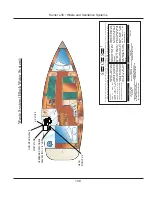
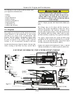
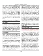
Fig. 11.1 shows you drive and components aboard your
boat.
We strongly urge you to comply with the manual pro-
vided by the engine manufacturer. Follow the recom-
mended maintenance and warranty schedule in the
owner’s packet. Engine abuse or improper maintenance
may adversely affect the claims made under the inde-
pendent warranty provided by the engine manufacturer.
The engine manual states the maximum RPM rating
established by the engine manufacturer for your boat’s
engines. Do not exceed this rating. Check the manual
for other information about maximum RPM’s.
Engines are selected and designed to meet or exceed
industry standards set by marine engine manufacturers.
HOSES TO
WATER HTR.
ENGINE
ENGINE
MUFFLER
MUFFLER
HULL BOTTOM
SYSTEMS SCHEMATIC FOR STERN DRIVE ENGINE
ENGINE
ELECTRICAL
SYSTEM
WATER INTAKE
EXHAUST
FUEL SYSTEM
FEED
RETURN
TANK
FILTER
VALVE @ TANK
RUNNING GEAR
SHAFT
COUPLING
DRIPLESS
THRU-HULL
SEA COCK
STRAINER
ELBOW
HOSE
MUFFLER
CONTROLS
SHIFT
THROTTLE
PANEL HARNESS
BATT SW
STARTING BATTERY
HOUSE BATTERY
OPT. INVERTER
12V SYSTEM
110V SYSTEM
SHORE POWER
STARTING SYSTEM
HOUSE SYSTEM
FUEL FEED & FILTER
STUFFING BOX/SHAFT
RAW WATER FEED
COMPARTMENT ENCLOSURE
COOLANT
RESV.
BATTERY
BATT. SWITCH
DC
PANEL
COOLANT
RESV.
A.C.
PANEL
SHORE PWR
TO
APPLIANCES
OPT.
BATT. CHGR.
INV.PANEL
HOSES TO
WAT.HTR.
ENGINE ENCLOSURE
RAW WTR.FEED W/STRAINER
FUEL RETURN
FUEL FEED W/FILTER
SHIFT CABLE
THROTTLE CABLE
ENGINE STOP CABLE
INSTUMT. PANEL WIRE HARNESS
CONTROL
CABLES TO
PEDESTAL
TO
FUEL
TANK
SEE ELEVATION BELOW FOR CABLES TO PEDESTAL
SEE PLAN ABOVE FOR PROP SHAFT & STUFFING BOX
NOTE: THIS DWG. IS GENERIC SCHEMATIC FORM
HEAT EXCHANGE
BLEEDER VALVE
BATTERY
(FLEX SHUT OFF)
/ INVTR.
RETURN FUEL LINE
PLAN
ELEVATION
Fig. 11.1
Summary of Contents for e36
Page 1: ...V2 062012 Operator s Manual e 36 ...
Page 2: ......
Page 9: ...V2 062012 Introduction e 36 Chapter 1 ...
Page 14: ...Hunter e36 Introduction 1 6 Notes ...
Page 15: ...Documents Forms e 36 Chapter 2 and V2 062012 ...
Page 26: ...Hunter e36 Documents and Forms Maintenance Log Date Maintenance Performed Hourmeter 2 12 ...
Page 27: ...Hunter e36 Documents and Forms 2 13 Date Maintenance Performed Hourmeter Maintenance Log ...
Page 33: ...Hunter e36 Documents and Forms 2 19 Spare Parts List ...
Page 34: ...Hunter e36 Documents and Forms Dates of practice drills and onboard safety inspections 2 20 ...
Page 35: ...Hunter e36 Documents and Forms 2 21 My personal preferences for maintenance items safety gear ...
Page 36: ...Hunter e36 Documents and Forms Notes 2 22 ...
Page 37: ...V2 062012 Limited Warranty e 36 Chapter 3 ...
Page 38: ...This Page Intentionally Left Blank Hunter Limited Warranty 3 2 ...
Page 47: ...Boating Safety e 36 Chapter 4 V2 062012 ...
Page 65: ...Deck Hardware Hunter e36 Boating Safety 4 19 ...
Page 67: ...Hunter e36 Boating Safety 4 21 Notes ...
Page 68: ...Hunter e36 Boating Safety 4 22 Notes ...
Page 69: ...V2 062012 Fuel Systems e 36 Chapter 5 ...
Page 75: ...Fig 5 7 A Quick Fuel Filter Reference Hunter e36 Fuel Systems 5 7 ...
Page 82: ...Notes Hunter e36 Fuel Systems 5 14 ...
Page 83: ...V2 062012 Underwater Gear e 36 Chapter 6 ...
Page 92: ...Hunter e36 Underwater Gear 6 10 Notes ...
Page 93: ...V2 062012 DC Electric Systems e 36 Chapter 7 ...
Page 103: ...Hunter e36 DC Electric 7 11 7 8 BASIC DC POWER SUPPLY SYSTEM DIAGRAM ...
Page 104: ...Hunter e36 DC Electric 7 12 Notes ...
Page 106: ...Hunter e36 DC Electric 7 14 Notes ...
Page 107: ...V2 062012 AC Electric Systems e 36 Chapter 8 ...
Page 115: ...Hunter e36 AC Electric Systems 8 9 7 8 AC DC Electric Power Supply Diagram ...
Page 116: ...Hunter e36 AC Electric Systems 8 10 This Page Intentionally Left Blank ...
Page 117: ...Hunter e36 AC Electric Systems 8 11 Notes ...
Page 118: ...Hunter e36 AC Electric Systems 8 12 Notes ...
Page 119: ...V2 062012 Water Systems e 36 Chapter 9 ...
Page 126: ...Hunter e36 Water Systems 9 8 This Page Intentionally Left Blank ...
Page 128: ...Hunter e36 Water Systems 9 10 This Page Intentionally Left Blank ...
Page 129: ...Hunter e36 Water Systems 9 11 Notes ...
Page 130: ...Hunter e36 Water Systems 9 12 Notes ...
Page 131: ...V2 062012 Waste Systems e 36 Chapter 10 ...
Page 137: ...Hunter e36 Waste and Sanitation Systems 10 7 ...
Page 140: ...This Page Intentionally Left Blank Hunter e36 Waste and Sanitation Systems 10 10 ...
Page 141: ...Sump Pump Layout Grey Water Hunter e36 Waste and Sanitation Systems 10 11 ...
Page 142: ...This Page Intentionally Left Blank Hunter e36 Waste and Sanitation Systems 10 12 ...
Page 144: ...Hunter e36 Waste and Sanitation Systems 10 14 Notes ...
Page 145: ...V2 062012 Engines Transmissions e 36 Chapter 11 and ...
Page 154: ...Hunter e36 Engines and Transmissions 11 10 This Page Intentional Left Blank ...
Page 155: ...V2 062012 Sails Rigging e 36 Chapter 12 and ...
Page 162: ...Hunter e36 Sails and Rigging 12 8 Standing Rigging Details Standard ...
Page 163: ...Hunter e36 Sails and Rigging 12 9 Standing Rigging Details Furling ...
Page 164: ...Hunter e36 Sails and Rigging 12 10 Mast Upper Spreader Tip Details H A B C D E F G ...
Page 165: ...Hunter e36 Sails and Rigging 12 11 C A B D E F G H J K I Mast Lower Spreader Tip Details ...
Page 166: ...Hunter e36 Sails and Rigging 12 12 Standing Rigging Details ...
Page 170: ...Hunter e36 Sails and Rigging 12 16 Typical Boom Reefing Layout ...
Page 171: ...Hunter e36 Sails and Rigging 12 17 Rope Vang Details Standard Vang Details ...
Page 172: ...Hunter e36 Sails and Rigging 12 18 Rigid Vang Details Optional Vang Details ...
Page 175: ...Hunter e36 Sails and Rigging 12 21 JIB LINE TIES OFF ON CLEAT Jib Furling Line Layout ...
Page 176: ...Hunter e36 Sails and Rigging 12 22 Bridle Configuration ...
Page 179: ...Hunter e36 Sails and Rigging 12 25 Optional Spinnaker Layout ...
Page 180: ...Hunter e36 Sails and Rigging 12 26 Notes ...
Page 181: ...V2 062012 Getting Underway e 36 Chapter 13 ...
Page 188: ...Hunter e36 Getting Underway 13 8 Notes ...
Page 189: ...V2 062012 Maintenance e 36 Chapter 14 ...
Page 202: ...Notes Hunter e36 Maintenance 14 14 ...
Page 203: ...Exterior Lifting Points Hunter e36 Maintenance 14 15 ...
Page 204: ...Hunter e36 Maintenance 14 16 This Page Intentionally Left Blank ...