


In the event of a major leak, contact the appropriate
authorities.
Small quantities of spilled liquid may be allowed to evapo-
rate. Vapor should be dispersed by effective ventilation.
5.5.5 Handling and Storage
Store and use only in equipment/containers for use with
your particular appliance. Tanks should only be stored in
a locker installed and designed for LPG storage, outside
the living areas of the boat.
Installation or added appliances should only be per-
formed by qualified personnel.
Follow manufacturer’s instructions for changing tanks.
Ensure good ventilation.
Avoid inhalation of vapor.
When handling cylinders, wear protective footwear and
suitable gloves.
When handling cylinders (above head height) protective
headgear may be necessary.
When changing tanks, wear suitable gloves and safety
goggles or face shields.
Avoid contact with the eyes.
5.5.6 Exposure Controls / Personal Protection
Skin Protection – Wear suitable protective overalls
with long sleeves to cover exposed skin.
Eye Protection – Use chemical goggles or face shield
when changing tanks.
Hand Protection – Use impervious gloves when
changing tanks.
Use suitable protective gloves when handling cylin-
ders.
Foot Protection – Wear safety boots or shoes when
handling cylinders.
Head Protection – When handling cylinders above
head heights, protective headgear may be necessary.
•
•
•
•
•
•
5.5.8 Stability and Reactivity
Stable at ambient temperatures.
Hazardous polymerization reactions will not occur.
5.5.9 Material to Avoid
Avoid contact with strong oxidizing agents.
5.5.10 Hazardous Decomposition Products
Normally Carbon Dioxide.
Incomplete combustion will generate Carbon Monoxide.
See the Boating Safety Chapter for more information on
Carbon Monoxide.
Note: Can form explosive mixture with air.
5.5.11 Toxicological Information
Eyes: Will present a risk of serious damage to the eyes
if contact with liquid or vapor pressure jet occurs.
Skin: Will cause cold burns (frostbite) if skin contact
with liquid occurs.
Fig. 5.8 Exposure Limits
Long Term Exposure
Limit (PPM) (8 hr
TWA)
Short Term Exposure
Limit (PPM) (10 min
period)
Butane
600
750
LPG
1000
1250
Propane
None Established. Considered to be an asphyxi-
ate at high concentration in air
(source: India LPG)
Inhalation: Low vapor concentrations may cause nausea,
dizziness, headaches, and drowsiness. High vapor con-
centrations may produce symptoms of oxygen deficiency
which, coupled with central nervous system depression,
may lead to rapid loss of consciousness.
ABUSE: Under normal conditions of use, the product is
not hazardous. Abuse involving deliberate inhalation of
very high concentrations of vapor, even for short periods,
can produce unconsciousness and/or result in a sudden
fatality.
Hunter e36 • Fuel Systems
5.9
Summary of Contents for e36
Page 1: ...V2 062012 Operator s Manual e 36 ...
Page 2: ......
Page 9: ...V2 062012 Introduction e 36 Chapter 1 ...
Page 14: ...Hunter e36 Introduction 1 6 Notes ...
Page 15: ...Documents Forms e 36 Chapter 2 and V2 062012 ...
Page 26: ...Hunter e36 Documents and Forms Maintenance Log Date Maintenance Performed Hourmeter 2 12 ...
Page 27: ...Hunter e36 Documents and Forms 2 13 Date Maintenance Performed Hourmeter Maintenance Log ...
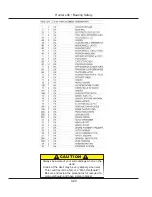
Page 33: ...Hunter e36 Documents and Forms 2 19 Spare Parts List ...
Page 34: ...Hunter e36 Documents and Forms Dates of practice drills and onboard safety inspections 2 20 ...
Page 35: ...Hunter e36 Documents and Forms 2 21 My personal preferences for maintenance items safety gear ...
Page 36: ...Hunter e36 Documents and Forms Notes 2 22 ...
Page 37: ...V2 062012 Limited Warranty e 36 Chapter 3 ...
Page 38: ...This Page Intentionally Left Blank Hunter Limited Warranty 3 2 ...
Page 47: ...Boating Safety e 36 Chapter 4 V2 062012 ...
Page 65: ...Deck Hardware Hunter e36 Boating Safety 4 19 ...
Page 67: ...Hunter e36 Boating Safety 4 21 Notes ...
Page 68: ...Hunter e36 Boating Safety 4 22 Notes ...
Page 69: ...V2 062012 Fuel Systems e 36 Chapter 5 ...
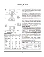
Page 75: ...Fig 5 7 A Quick Fuel Filter Reference Hunter e36 Fuel Systems 5 7 ...
Page 82: ...Notes Hunter e36 Fuel Systems 5 14 ...
Page 83: ...V2 062012 Underwater Gear e 36 Chapter 6 ...
Page 92: ...Hunter e36 Underwater Gear 6 10 Notes ...
Page 93: ...V2 062012 DC Electric Systems e 36 Chapter 7 ...
Page 103: ...Hunter e36 DC Electric 7 11 7 8 BASIC DC POWER SUPPLY SYSTEM DIAGRAM ...
Page 104: ...Hunter e36 DC Electric 7 12 Notes ...
Page 106: ...Hunter e36 DC Electric 7 14 Notes ...
Page 107: ...V2 062012 AC Electric Systems e 36 Chapter 8 ...
Page 115: ...Hunter e36 AC Electric Systems 8 9 7 8 AC DC Electric Power Supply Diagram ...
Page 116: ...Hunter e36 AC Electric Systems 8 10 This Page Intentionally Left Blank ...
Page 117: ...Hunter e36 AC Electric Systems 8 11 Notes ...
Page 118: ...Hunter e36 AC Electric Systems 8 12 Notes ...
Page 119: ...V2 062012 Water Systems e 36 Chapter 9 ...
Page 126: ...Hunter e36 Water Systems 9 8 This Page Intentionally Left Blank ...
Page 128: ...Hunter e36 Water Systems 9 10 This Page Intentionally Left Blank ...
Page 129: ...Hunter e36 Water Systems 9 11 Notes ...
Page 130: ...Hunter e36 Water Systems 9 12 Notes ...
Page 131: ...V2 062012 Waste Systems e 36 Chapter 10 ...
Page 137: ...Hunter e36 Waste and Sanitation Systems 10 7 ...
Page 140: ...This Page Intentionally Left Blank Hunter e36 Waste and Sanitation Systems 10 10 ...
Page 141: ...Sump Pump Layout Grey Water Hunter e36 Waste and Sanitation Systems 10 11 ...
Page 142: ...This Page Intentionally Left Blank Hunter e36 Waste and Sanitation Systems 10 12 ...
Page 144: ...Hunter e36 Waste and Sanitation Systems 10 14 Notes ...
Page 145: ...V2 062012 Engines Transmissions e 36 Chapter 11 and ...
Page 154: ...Hunter e36 Engines and Transmissions 11 10 This Page Intentional Left Blank ...
Page 155: ...V2 062012 Sails Rigging e 36 Chapter 12 and ...
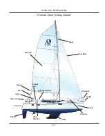
Page 162: ...Hunter e36 Sails and Rigging 12 8 Standing Rigging Details Standard ...
Page 163: ...Hunter e36 Sails and Rigging 12 9 Standing Rigging Details Furling ...
Page 164: ...Hunter e36 Sails and Rigging 12 10 Mast Upper Spreader Tip Details H A B C D E F G ...
Page 165: ...Hunter e36 Sails and Rigging 12 11 C A B D E F G H J K I Mast Lower Spreader Tip Details ...
Page 166: ...Hunter e36 Sails and Rigging 12 12 Standing Rigging Details ...
Page 170: ...Hunter e36 Sails and Rigging 12 16 Typical Boom Reefing Layout ...
Page 171: ...Hunter e36 Sails and Rigging 12 17 Rope Vang Details Standard Vang Details ...
Page 172: ...Hunter e36 Sails and Rigging 12 18 Rigid Vang Details Optional Vang Details ...
Page 175: ...Hunter e36 Sails and Rigging 12 21 JIB LINE TIES OFF ON CLEAT Jib Furling Line Layout ...
Page 176: ...Hunter e36 Sails and Rigging 12 22 Bridle Configuration ...
Page 179: ...Hunter e36 Sails and Rigging 12 25 Optional Spinnaker Layout ...
Page 180: ...Hunter e36 Sails and Rigging 12 26 Notes ...
Page 181: ...V2 062012 Getting Underway e 36 Chapter 13 ...
Page 188: ...Hunter e36 Getting Underway 13 8 Notes ...
Page 189: ...V2 062012 Maintenance e 36 Chapter 14 ...
Page 202: ...Notes Hunter e36 Maintenance 14 14 ...
Page 203: ...Exterior Lifting Points Hunter e36 Maintenance 14 15 ...
Page 204: ...Hunter e36 Maintenance 14 16 This Page Intentionally Left Blank ...