


Hunter e36 • Underwater Gear
6.4
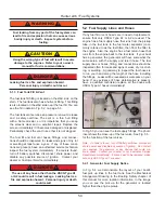
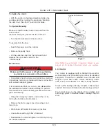
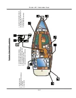
6.2.2 Rudders
Your Hunter rudder is constructed with a foam filled
composite blade by hand lay-up connected to an internal
stainless steel grid and rudder stock structure. The rud-
der bearings are self lubricating type bearings. Ensure
to inspect the free
and smooth opera-
tion of the rudder
stock and bearings
at regular intervals.
Fig. 6.5 shows
you a view at the
rudder under your
boat.
Your steering
system is a very
important part of
your boat and very
important to your
boating safety.
However, all boat
operator’s should
be prepared for
rudder failure or
loss. That is why
Hunter Marine has
a backup rudder
system that can be purchased for our current
models. Other commercial suppliers offer similar sys-
tems at differing benefits and costs. You should conduct
your own analysis to determine which alternative is best
for you.
CAUTION
!
!
Because the backup system can also be lost an
operator must be able to sail without a rudder or oth-
erwise be prepared to assemble a makeshift rudder.
Important: Look to the Getting Underway Chapter (chapter 12)
for information about using your emergency tiller system. The
connections and use are detailed in that section.
The next Figure in this section will allow you to observe
the cross section illustration of the rudder installed on
your boat. This view also shows you the upper and
lower rudder bearings.
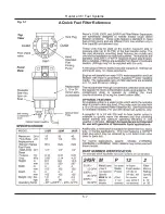
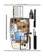
6.3 Seawater Intake
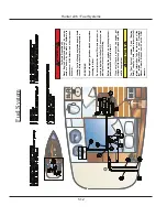
6.3.1 Skin Fittings and Intakes
On the bottom of your boat, you will find skin fittings and
intakes for the supply and discharge to your boat’s vari-
ous systems.
Care should be taken that these intakes and skin fittings
are cleaned of barnacles and other growth as specified
in the maintenance section of this manual to maintain a
clear, open passageway.
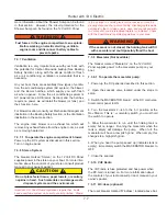
STREET ELL
TYP. THRU-HULL W/ SEACOCK DETAIL
THROUGH HULL
THROUGH HULL NUT
HOSE BARB
3/4 (19 MM)
PLYWOOD BACKING
HULL
DOUBLE CLAMPED
HOSE
BALL VALVE
TYP. THRU-HULL W/ SEACOCK DETAIL
The optional electronics package you have ordered on
your boat will largely determine the underwater gear that
is related to the monitoring equipment. Be sure and refer
to your documentation in your owner’s packet to find out
the details about this equipment.
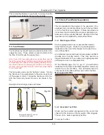
6.4 Windlass and Anchoring (Option)
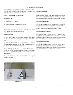
6.4.1 Windlass
The windlass facilitates the anchoring of your boat by
automatically raising and lowering the anchor. To oper-
ate the windlass, the windlass power switch at the Nav
station must be switched on.
Note: It is important that the windlass clutch is tight for proper
operation and safety. Periodically check the clutch and tighten
if necessary.
Fig. 6.6
Fig. 6.5
Summary of Contents for e36
Page 1: ...V2 062012 Operator s Manual e 36 ...
Page 2: ......
Page 9: ...V2 062012 Introduction e 36 Chapter 1 ...
Page 14: ...Hunter e36 Introduction 1 6 Notes ...
Page 15: ...Documents Forms e 36 Chapter 2 and V2 062012 ...
Page 26: ...Hunter e36 Documents and Forms Maintenance Log Date Maintenance Performed Hourmeter 2 12 ...
Page 27: ...Hunter e36 Documents and Forms 2 13 Date Maintenance Performed Hourmeter Maintenance Log ...
Page 33: ...Hunter e36 Documents and Forms 2 19 Spare Parts List ...
Page 34: ...Hunter e36 Documents and Forms Dates of practice drills and onboard safety inspections 2 20 ...
Page 35: ...Hunter e36 Documents and Forms 2 21 My personal preferences for maintenance items safety gear ...
Page 36: ...Hunter e36 Documents and Forms Notes 2 22 ...
Page 37: ...V2 062012 Limited Warranty e 36 Chapter 3 ...
Page 38: ...This Page Intentionally Left Blank Hunter Limited Warranty 3 2 ...
Page 47: ...Boating Safety e 36 Chapter 4 V2 062012 ...
Page 65: ...Deck Hardware Hunter e36 Boating Safety 4 19 ...
Page 67: ...Hunter e36 Boating Safety 4 21 Notes ...
Page 68: ...Hunter e36 Boating Safety 4 22 Notes ...
Page 69: ...V2 062012 Fuel Systems e 36 Chapter 5 ...
Page 75: ...Fig 5 7 A Quick Fuel Filter Reference Hunter e36 Fuel Systems 5 7 ...
Page 82: ...Notes Hunter e36 Fuel Systems 5 14 ...
Page 83: ...V2 062012 Underwater Gear e 36 Chapter 6 ...
Page 92: ...Hunter e36 Underwater Gear 6 10 Notes ...
Page 93: ...V2 062012 DC Electric Systems e 36 Chapter 7 ...
Page 103: ...Hunter e36 DC Electric 7 11 7 8 BASIC DC POWER SUPPLY SYSTEM DIAGRAM ...
Page 104: ...Hunter e36 DC Electric 7 12 Notes ...
Page 106: ...Hunter e36 DC Electric 7 14 Notes ...
Page 107: ...V2 062012 AC Electric Systems e 36 Chapter 8 ...
Page 115: ...Hunter e36 AC Electric Systems 8 9 7 8 AC DC Electric Power Supply Diagram ...
Page 116: ...Hunter e36 AC Electric Systems 8 10 This Page Intentionally Left Blank ...
Page 117: ...Hunter e36 AC Electric Systems 8 11 Notes ...
Page 118: ...Hunter e36 AC Electric Systems 8 12 Notes ...
Page 119: ...V2 062012 Water Systems e 36 Chapter 9 ...
Page 126: ...Hunter e36 Water Systems 9 8 This Page Intentionally Left Blank ...
Page 128: ...Hunter e36 Water Systems 9 10 This Page Intentionally Left Blank ...
Page 129: ...Hunter e36 Water Systems 9 11 Notes ...
Page 130: ...Hunter e36 Water Systems 9 12 Notes ...
Page 131: ...V2 062012 Waste Systems e 36 Chapter 10 ...
Page 137: ...Hunter e36 Waste and Sanitation Systems 10 7 ...
Page 140: ...This Page Intentionally Left Blank Hunter e36 Waste and Sanitation Systems 10 10 ...
Page 141: ...Sump Pump Layout Grey Water Hunter e36 Waste and Sanitation Systems 10 11 ...
Page 142: ...This Page Intentionally Left Blank Hunter e36 Waste and Sanitation Systems 10 12 ...
Page 144: ...Hunter e36 Waste and Sanitation Systems 10 14 Notes ...
Page 145: ...V2 062012 Engines Transmissions e 36 Chapter 11 and ...
Page 154: ...Hunter e36 Engines and Transmissions 11 10 This Page Intentional Left Blank ...
Page 155: ...V2 062012 Sails Rigging e 36 Chapter 12 and ...
Page 162: ...Hunter e36 Sails and Rigging 12 8 Standing Rigging Details Standard ...
Page 163: ...Hunter e36 Sails and Rigging 12 9 Standing Rigging Details Furling ...
Page 164: ...Hunter e36 Sails and Rigging 12 10 Mast Upper Spreader Tip Details H A B C D E F G ...
Page 165: ...Hunter e36 Sails and Rigging 12 11 C A B D E F G H J K I Mast Lower Spreader Tip Details ...
Page 166: ...Hunter e36 Sails and Rigging 12 12 Standing Rigging Details ...
Page 170: ...Hunter e36 Sails and Rigging 12 16 Typical Boom Reefing Layout ...
Page 171: ...Hunter e36 Sails and Rigging 12 17 Rope Vang Details Standard Vang Details ...
Page 172: ...Hunter e36 Sails and Rigging 12 18 Rigid Vang Details Optional Vang Details ...
Page 175: ...Hunter e36 Sails and Rigging 12 21 JIB LINE TIES OFF ON CLEAT Jib Furling Line Layout ...
Page 176: ...Hunter e36 Sails and Rigging 12 22 Bridle Configuration ...
Page 179: ...Hunter e36 Sails and Rigging 12 25 Optional Spinnaker Layout ...
Page 180: ...Hunter e36 Sails and Rigging 12 26 Notes ...
Page 181: ...V2 062012 Getting Underway e 36 Chapter 13 ...
Page 188: ...Hunter e36 Getting Underway 13 8 Notes ...
Page 189: ...V2 062012 Maintenance e 36 Chapter 14 ...
Page 202: ...Notes Hunter e36 Maintenance 14 14 ...
Page 203: ...Exterior Lifting Points Hunter e36 Maintenance 14 15 ...
Page 204: ...Hunter e36 Maintenance 14 16 This Page Intentionally Left Blank ...