


Hunter e36 • AC Electric Systems
8.5
DANGER
!
!
Fuel leaking from any part of the fuel system can
lead to fire and explosion that can cause serious
bodily injury or death. Inspect system before start-
ing engines.
DANGER
!
!
Never enter the engine compartment without proper
ventilation first. A spark caused by power tools or
lighting equipment could result in fire or explosion
which could cause personal injury or death.
DANGER
!
!
As with any fuel burning engine, Carbon Monoxide
is a concern. Read the Boating Safety section of
this manual, and educate yourself about Carbon
Monoxide poisoning. It could mean the difference in
your life and the life of your loved ones.
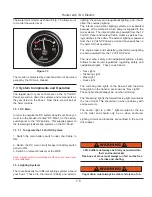
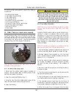
8.1.6.2 Generator Startup
1. To gain access to the generator open open hatch
to euro locker. Check generator for signs of fuel or oil
leaks.
2. Open fuel shutoff valve to generator.
3. Check generator oil level. Refer to the genrator manual
for instructions. Add oil if necessary.
4. Check generator coolant level See generator manual
for instructions.
5. Open generator seacock. Refer to locator drawing for
seacock location.
6. At generator control panel, turn all 120 VAC breakers
OFF. Make sure slide bar is moved up to lock out shore
power breakers.
7. Press and hold in generator start-stop switch to start.
Release switch as soon as the generator engine begins
running.
Important: Do not crank generator continuously for more
than 10 seconds, release switch. Allow starter motor to
cool for at least 10 seconds. Then try starting the engine
again. If generator fails to start after three attempts, con-
tact your Hunter dealer. Prolonged starting attempts may
damage starter motor as well as the generator.
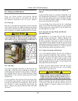
8. Inspect the exhaust system for leaks. If you detect
leaks or smell fumes, shut down the generator imme-
diately. Do not restart the generator until you have cor-
rected the problem.
8. Allow the generator to warm up before connecting a
heavy electrical load. Keep the load within the nameplate
rating.
Note: Infrequent use of the generator may result in hard
starting. For detailed startup information, refer to genrator
operating manual.
8.1.6.3 Generator Shutdown
1. Shut off all AC devices and equipment, and the shore
power / generator selector switch.
2. Allow generator to run for one to two minutes at no load
to allow the engine to cool down.
3. Press GENERATOR Start/Stop switch to STOP.
4. Close fuel valve and seacock.
8.1.7 Breakers, Switches, and Fuses
All electrical systems aboard your boat are provided with
over-current protection in the form of breakers or fuses.
Examples of breakers are the system or component con-
trols at the AC Distribution Panel, or systems that would
normally require you to energize them for use and are
provided with switches.
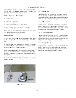
8.1.8 Battery Charger
The boat’s batteries are normally charged whenever the
engines are running. If you are docked for an extended
period of time, operating DC devices and equipment will
drain the power from the batteries. Unless the batteries
are kept charged, they may not have enough power to
start the engines when you need them.
The battery charger will automatically charge the engine
batteries and the generator battery when the power
supply is through the AC system. The battery charger
breaker is at the AC Distribution Panel.
Leaving the battery charger on whenever AC power is
available is a good idea. It will keep the batteries fully
Summary of Contents for e36
Page 1: ...V2 062012 Operator s Manual e 36 ...
Page 2: ......
Page 9: ...V2 062012 Introduction e 36 Chapter 1 ...
Page 14: ...Hunter e36 Introduction 1 6 Notes ...
Page 15: ...Documents Forms e 36 Chapter 2 and V2 062012 ...
Page 26: ...Hunter e36 Documents and Forms Maintenance Log Date Maintenance Performed Hourmeter 2 12 ...
Page 27: ...Hunter e36 Documents and Forms 2 13 Date Maintenance Performed Hourmeter Maintenance Log ...
Page 33: ...Hunter e36 Documents and Forms 2 19 Spare Parts List ...
Page 34: ...Hunter e36 Documents and Forms Dates of practice drills and onboard safety inspections 2 20 ...
Page 35: ...Hunter e36 Documents and Forms 2 21 My personal preferences for maintenance items safety gear ...
Page 36: ...Hunter e36 Documents and Forms Notes 2 22 ...
Page 37: ...V2 062012 Limited Warranty e 36 Chapter 3 ...
Page 38: ...This Page Intentionally Left Blank Hunter Limited Warranty 3 2 ...
Page 47: ...Boating Safety e 36 Chapter 4 V2 062012 ...
Page 65: ...Deck Hardware Hunter e36 Boating Safety 4 19 ...
Page 67: ...Hunter e36 Boating Safety 4 21 Notes ...
Page 68: ...Hunter e36 Boating Safety 4 22 Notes ...
Page 69: ...V2 062012 Fuel Systems e 36 Chapter 5 ...
Page 75: ...Fig 5 7 A Quick Fuel Filter Reference Hunter e36 Fuel Systems 5 7 ...
Page 82: ...Notes Hunter e36 Fuel Systems 5 14 ...
Page 83: ...V2 062012 Underwater Gear e 36 Chapter 6 ...
Page 92: ...Hunter e36 Underwater Gear 6 10 Notes ...
Page 93: ...V2 062012 DC Electric Systems e 36 Chapter 7 ...
Page 103: ...Hunter e36 DC Electric 7 11 7 8 BASIC DC POWER SUPPLY SYSTEM DIAGRAM ...
Page 104: ...Hunter e36 DC Electric 7 12 Notes ...
Page 106: ...Hunter e36 DC Electric 7 14 Notes ...
Page 107: ...V2 062012 AC Electric Systems e 36 Chapter 8 ...
Page 115: ...Hunter e36 AC Electric Systems 8 9 7 8 AC DC Electric Power Supply Diagram ...
Page 116: ...Hunter e36 AC Electric Systems 8 10 This Page Intentionally Left Blank ...
Page 117: ...Hunter e36 AC Electric Systems 8 11 Notes ...
Page 118: ...Hunter e36 AC Electric Systems 8 12 Notes ...
Page 119: ...V2 062012 Water Systems e 36 Chapter 9 ...
Page 126: ...Hunter e36 Water Systems 9 8 This Page Intentionally Left Blank ...
Page 128: ...Hunter e36 Water Systems 9 10 This Page Intentionally Left Blank ...
Page 129: ...Hunter e36 Water Systems 9 11 Notes ...
Page 130: ...Hunter e36 Water Systems 9 12 Notes ...
Page 131: ...V2 062012 Waste Systems e 36 Chapter 10 ...
Page 137: ...Hunter e36 Waste and Sanitation Systems 10 7 ...
Page 140: ...This Page Intentionally Left Blank Hunter e36 Waste and Sanitation Systems 10 10 ...
Page 141: ...Sump Pump Layout Grey Water Hunter e36 Waste and Sanitation Systems 10 11 ...
Page 142: ...This Page Intentionally Left Blank Hunter e36 Waste and Sanitation Systems 10 12 ...
Page 144: ...Hunter e36 Waste and Sanitation Systems 10 14 Notes ...
Page 145: ...V2 062012 Engines Transmissions e 36 Chapter 11 and ...
Page 154: ...Hunter e36 Engines and Transmissions 11 10 This Page Intentional Left Blank ...
Page 155: ...V2 062012 Sails Rigging e 36 Chapter 12 and ...
Page 162: ...Hunter e36 Sails and Rigging 12 8 Standing Rigging Details Standard ...
Page 163: ...Hunter e36 Sails and Rigging 12 9 Standing Rigging Details Furling ...
Page 164: ...Hunter e36 Sails and Rigging 12 10 Mast Upper Spreader Tip Details H A B C D E F G ...
Page 165: ...Hunter e36 Sails and Rigging 12 11 C A B D E F G H J K I Mast Lower Spreader Tip Details ...
Page 166: ...Hunter e36 Sails and Rigging 12 12 Standing Rigging Details ...
Page 170: ...Hunter e36 Sails and Rigging 12 16 Typical Boom Reefing Layout ...
Page 171: ...Hunter e36 Sails and Rigging 12 17 Rope Vang Details Standard Vang Details ...
Page 172: ...Hunter e36 Sails and Rigging 12 18 Rigid Vang Details Optional Vang Details ...
Page 175: ...Hunter e36 Sails and Rigging 12 21 JIB LINE TIES OFF ON CLEAT Jib Furling Line Layout ...
Page 176: ...Hunter e36 Sails and Rigging 12 22 Bridle Configuration ...
Page 179: ...Hunter e36 Sails and Rigging 12 25 Optional Spinnaker Layout ...
Page 180: ...Hunter e36 Sails and Rigging 12 26 Notes ...
Page 181: ...V2 062012 Getting Underway e 36 Chapter 13 ...
Page 188: ...Hunter e36 Getting Underway 13 8 Notes ...
Page 189: ...V2 062012 Maintenance e 36 Chapter 14 ...
Page 202: ...Notes Hunter e36 Maintenance 14 14 ...
Page 203: ...Exterior Lifting Points Hunter e36 Maintenance 14 15 ...
Page 204: ...Hunter e36 Maintenance 14 16 This Page Intentionally Left Blank ...