


Hunter e36 • DC Electric
7.4
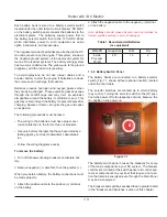
7.2.3 Battery Charging System
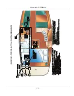
Refer to the DC Wiring Diagram drawing at the end of
this section for the location of the battery charger. The
charger is protected by a fuse on the positive and ground
side at the charger.
To operate the charger, ensure that it is operating:
Connect the shore power dockside supply shore
power inlet on the stern of the boat on the port side.
Turn on AC Main breaker.
Turn on the Battery Charger breaker.
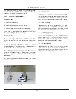
7.2.4 12 Volt DC Panel
ANCHOR LT
RUNNING LIGHTS
WATER PUMP
BLOWER
VOLTS
GPS
TV/DVD
STEREO
PANEL
LTS
BILGE
PUMP
SPARE
HEAD
12V DC
SUMP PUMP
REFRIGERATOR
LPG
OFF
OFF
OFF
OFF
OFF
OFF
CABIN LIGHTS
12V OUTLETS
TANK INDICATOR
MACERATOR
INSTRUMENTS
STEAMING LT
Figure 7.2
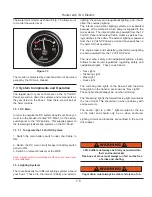
You can view the DC components controlled by the DC
control panel here (Fig. 7.2). Notice when the battery
selector switch is switched on the respective voltage of
the battery is shown on the right by the digital volt meter.
Indicator lights are built into most switches and alert you
that the selected system is powered.
7.2.5 Breakers, Switches, and Fuses
1.
2.
3.
All electrical systems aboard your boat are provided with
over-current protection in the form of breakers or fuses.
Examples of breakers are the system or component con-
trols at the 12 Volt Panel, or in the battery selector switch
panel. Systems that would normally require you to ener-
gize them for use are provided with switches.
7.2.6 Inverter (Option)
Inverter converts DC power to AC.
7.2.6.1 Inverter Basic Operation
1. Turn the house battery switch to either the “1, 2 or
Both” positions
2. Turn on inverter remote panel at the Navigation
Station.
3. Turn on the appropriate appliance breaker on AC
Panel. Note: only Outlets and microwave operating using
the inverter.
See Inverter manual for technical data, troubleshooting,
etc. operatiing/programming instructions.
7.2.7 Generator (Option)
Although, technically, the generator is part of the AC
System, because it supplies AC power, however the start-
ing of the generator requires DC power. The generator
starting receives power from the start battery bank.
The generator supplies 120 volt 60 hz AC power for
operating devices and equipment controlled through the
AC Control Panel.
When the generator indicating light is on and the genera-
tor breakers are on, AC power is supplied to AC control
panel devices and equipment.
Refer to the “Operation and Procedures” part of the AC
Electric section for information on starting the generator.
You can find the location of the generator on the DC
Wiring Diagram drawing at the end of this chapter.
7.2.8 Water Systems
The water systems are outlined in the Water Systems
chapter in this manual. However, the monitor for this sys-
tem are powered by the DC Electrical system.
Summary of Contents for e36
Page 1: ...V2 062012 Operator s Manual e 36 ...
Page 2: ......
Page 9: ...V2 062012 Introduction e 36 Chapter 1 ...
Page 14: ...Hunter e36 Introduction 1 6 Notes ...
Page 15: ...Documents Forms e 36 Chapter 2 and V2 062012 ...
Page 26: ...Hunter e36 Documents and Forms Maintenance Log Date Maintenance Performed Hourmeter 2 12 ...
Page 27: ...Hunter e36 Documents and Forms 2 13 Date Maintenance Performed Hourmeter Maintenance Log ...
Page 33: ...Hunter e36 Documents and Forms 2 19 Spare Parts List ...
Page 34: ...Hunter e36 Documents and Forms Dates of practice drills and onboard safety inspections 2 20 ...
Page 35: ...Hunter e36 Documents and Forms 2 21 My personal preferences for maintenance items safety gear ...
Page 36: ...Hunter e36 Documents and Forms Notes 2 22 ...
Page 37: ...V2 062012 Limited Warranty e 36 Chapter 3 ...
Page 38: ...This Page Intentionally Left Blank Hunter Limited Warranty 3 2 ...
Page 47: ...Boating Safety e 36 Chapter 4 V2 062012 ...
Page 65: ...Deck Hardware Hunter e36 Boating Safety 4 19 ...
Page 67: ...Hunter e36 Boating Safety 4 21 Notes ...
Page 68: ...Hunter e36 Boating Safety 4 22 Notes ...
Page 69: ...V2 062012 Fuel Systems e 36 Chapter 5 ...
Page 75: ...Fig 5 7 A Quick Fuel Filter Reference Hunter e36 Fuel Systems 5 7 ...
Page 82: ...Notes Hunter e36 Fuel Systems 5 14 ...
Page 83: ...V2 062012 Underwater Gear e 36 Chapter 6 ...
Page 92: ...Hunter e36 Underwater Gear 6 10 Notes ...
Page 93: ...V2 062012 DC Electric Systems e 36 Chapter 7 ...
Page 103: ...Hunter e36 DC Electric 7 11 7 8 BASIC DC POWER SUPPLY SYSTEM DIAGRAM ...
Page 104: ...Hunter e36 DC Electric 7 12 Notes ...
Page 106: ...Hunter e36 DC Electric 7 14 Notes ...
Page 107: ...V2 062012 AC Electric Systems e 36 Chapter 8 ...
Page 115: ...Hunter e36 AC Electric Systems 8 9 7 8 AC DC Electric Power Supply Diagram ...
Page 116: ...Hunter e36 AC Electric Systems 8 10 This Page Intentionally Left Blank ...
Page 117: ...Hunter e36 AC Electric Systems 8 11 Notes ...
Page 118: ...Hunter e36 AC Electric Systems 8 12 Notes ...
Page 119: ...V2 062012 Water Systems e 36 Chapter 9 ...
Page 126: ...Hunter e36 Water Systems 9 8 This Page Intentionally Left Blank ...
Page 128: ...Hunter e36 Water Systems 9 10 This Page Intentionally Left Blank ...
Page 129: ...Hunter e36 Water Systems 9 11 Notes ...
Page 130: ...Hunter e36 Water Systems 9 12 Notes ...
Page 131: ...V2 062012 Waste Systems e 36 Chapter 10 ...
Page 137: ...Hunter e36 Waste and Sanitation Systems 10 7 ...
Page 140: ...This Page Intentionally Left Blank Hunter e36 Waste and Sanitation Systems 10 10 ...
Page 141: ...Sump Pump Layout Grey Water Hunter e36 Waste and Sanitation Systems 10 11 ...
Page 142: ...This Page Intentionally Left Blank Hunter e36 Waste and Sanitation Systems 10 12 ...
Page 144: ...Hunter e36 Waste and Sanitation Systems 10 14 Notes ...
Page 145: ...V2 062012 Engines Transmissions e 36 Chapter 11 and ...
Page 154: ...Hunter e36 Engines and Transmissions 11 10 This Page Intentional Left Blank ...
Page 155: ...V2 062012 Sails Rigging e 36 Chapter 12 and ...
Page 162: ...Hunter e36 Sails and Rigging 12 8 Standing Rigging Details Standard ...
Page 163: ...Hunter e36 Sails and Rigging 12 9 Standing Rigging Details Furling ...
Page 164: ...Hunter e36 Sails and Rigging 12 10 Mast Upper Spreader Tip Details H A B C D E F G ...
Page 165: ...Hunter e36 Sails and Rigging 12 11 C A B D E F G H J K I Mast Lower Spreader Tip Details ...
Page 166: ...Hunter e36 Sails and Rigging 12 12 Standing Rigging Details ...
Page 170: ...Hunter e36 Sails and Rigging 12 16 Typical Boom Reefing Layout ...
Page 171: ...Hunter e36 Sails and Rigging 12 17 Rope Vang Details Standard Vang Details ...
Page 172: ...Hunter e36 Sails and Rigging 12 18 Rigid Vang Details Optional Vang Details ...
Page 175: ...Hunter e36 Sails and Rigging 12 21 JIB LINE TIES OFF ON CLEAT Jib Furling Line Layout ...
Page 176: ...Hunter e36 Sails and Rigging 12 22 Bridle Configuration ...
Page 179: ...Hunter e36 Sails and Rigging 12 25 Optional Spinnaker Layout ...
Page 180: ...Hunter e36 Sails and Rigging 12 26 Notes ...
Page 181: ...V2 062012 Getting Underway e 36 Chapter 13 ...
Page 188: ...Hunter e36 Getting Underway 13 8 Notes ...
Page 189: ...V2 062012 Maintenance e 36 Chapter 14 ...
Page 202: ...Notes Hunter e36 Maintenance 14 14 ...
Page 203: ...Exterior Lifting Points Hunter e36 Maintenance 14 15 ...
Page 204: ...Hunter e36 Maintenance 14 16 This Page Intentionally Left Blank ...