Operation and Configuration
Loading a Disk
Chapter 3
3-10
Loading a Disk
Start with
READY
or
LOAD
in the display
.
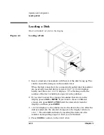
Figure 3-3
Loading a Disk
1. Insert a disk into the mailslot with Side A of the disk facing up. The
shutter end of the disk goes in the mailslot first.
When the disk is inserted, it is automatically pulled into the mailslot.
An incorrectly inserted disk is rejected,
CART IN WRONG
displays
briefly, and then
LOAD SLOT
# displays. (“#” is flashing and is the
number of the first available storage slot in the jukebox.)
2. If you want to select the storage slot number that shows in the
display, press
LOAD
or
ENTER
. If you want to choose a different
storage slot, press
NEXT
or
PREV
until the desired slot number
displays, and then press
ENTER
.
3.
LOADING
displays as the jukebox moves the disk to the slot. After the
disk is loaded into the selected storage slot, the display returns to
LOAD *
. YLoad additional disks by inserting the disks into the
mailslot and repeating steps 1-3 until you are finished.
4. Press
CANCEL
to return to the
READY
state.
Summary of Contents for Surestore 160ex - Optical Jukebox
Page 10: ...TOC x Contents ...
Page 14: ...Tables TOC xiv ...
Page 15: ...Chapter 1 1 1 Product Information 1 Product Information ...
Page 26: ...Product Information Environmental Specifications Chapter 1 1 12 ...
Page 27: ...Chapter 2 2 1 Installation 2 Installation ...
Page 30: ...Installation Identifying Controls and Features Chapter 2 2 4 Figure 2 2 Left Side ...
Page 47: ...Chapter 3 3 1 Operation and Configuration 3 Operation and Configuration ...
Page 75: ...Chapter 4 4 1 Troubleshooting and Diagnostics 4 Troubleshooting and Diagnostics ...
Page 122: ...Troubleshooting and Diagnostics Running an Internal Test Chapter 4 4 48 ...
Page 123: ...Chapter 5 5 1 Removal and Replacement 5 Removal and Replacement ...
Page 129: ...Removal and Replacement Service Access Chapter 5 5 7 Removal and Replacement Front Panel ...
Page 188: ...Removal and Replacement Replaceable Parts Chapter 5 5 66 Figure 5 43 Exploded View 1 of 3 ...
Page 190: ...Removal and Replacement Replaceable Parts Chapter 5 5 68 Figure 5 45 Exploded View 3 of 3 ...
Page 192: ...Removal and Replacement Replaceable Parts Chapter 5 5 70 Figure 5 47 Rope and Pulley System ...
Page 193: ...Chapter 6 6 1 Theory of Operation 6 Theory of Operation ...
Page 218: ...Theory of Operation Optical Drive Mechanism Chapter 6 6 26 ...
Page 219: ...Appendix A A 1 Safety and Regulatory A Safety and Regulatory Information ...


