Theory of Operation
Power Supplies
Chapter 6
6-11
T
h
eory
o
f Operat
io
n
Power Supplies
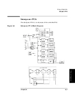
There are two autoranging power supplies.
• One su5 volts at 15 amperes and +12 volts at 10 amperes,
which powers the drives and the jukebox logic.
• The other supply pr24 volts at 5 amperes, which powers the
motors.
Figure 6-4
Power Supplies and Poweron Sequence
Line power is connected through the power distribution PCA in the
interface enclosure. Connection is direct to the 24-volt power supply.
When the 24-volt power supply comes up and is good AND if the power
standby switch on the right side of the jukebox is in the ON position, the
output of the 24-volt power supply is enabled. The 24-volt output closes
the relay on the power distribution PCA, allowing line power to be
applied to the 5/12-volt power supply for the jukebox.
The 24V power supply is equipped with a fan-detect circuit that turns
the supply off if the fans over the drives stop operating.
Summary of Contents for Surestore 160ex - Optical Jukebox
Page 10: ...TOC x Contents ...
Page 14: ...Tables TOC xiv ...
Page 15: ...Chapter 1 1 1 Product Information 1 Product Information ...
Page 26: ...Product Information Environmental Specifications Chapter 1 1 12 ...
Page 27: ...Chapter 2 2 1 Installation 2 Installation ...
Page 30: ...Installation Identifying Controls and Features Chapter 2 2 4 Figure 2 2 Left Side ...
Page 47: ...Chapter 3 3 1 Operation and Configuration 3 Operation and Configuration ...
Page 75: ...Chapter 4 4 1 Troubleshooting and Diagnostics 4 Troubleshooting and Diagnostics ...
Page 122: ...Troubleshooting and Diagnostics Running an Internal Test Chapter 4 4 48 ...
Page 123: ...Chapter 5 5 1 Removal and Replacement 5 Removal and Replacement ...
Page 129: ...Removal and Replacement Service Access Chapter 5 5 7 Removal and Replacement Front Panel ...
Page 188: ...Removal and Replacement Replaceable Parts Chapter 5 5 66 Figure 5 43 Exploded View 1 of 3 ...
Page 190: ...Removal and Replacement Replaceable Parts Chapter 5 5 68 Figure 5 45 Exploded View 3 of 3 ...
Page 192: ...Removal and Replacement Replaceable Parts Chapter 5 5 70 Figure 5 47 Rope and Pulley System ...
Page 193: ...Chapter 6 6 1 Theory of Operation 6 Theory of Operation ...
Page 218: ...Theory of Operation Optical Drive Mechanism Chapter 6 6 26 ...
Page 219: ...Appendix A A 1 Safety and Regulatory A Safety and Regulatory Information ...


