Theory of Operation
Picker
Chapter 6
6-20
Picker
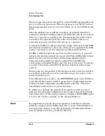
The picker in this jukebox is capable of holding two disk cartridges at
once. Its two thumbs can be addressed in two ways:
• Address the picker in single-picker mode,
• Address the picker in dual-picker mode.
Single-picker Mode
In single-picker mode, the picker is addressed as a single element
number. Since the driver cannot address each thumb individually, the
firmware makes the best choice for which thumb to use.
SCSI commands, such as Read Element Status and Mode Sense, report
back a single element address for the transport element. In this jukebox,
the single element address is 0.
Dual-picker Mode
In dual-picker mode, each thumb on the picker is considered an element
and is addressed individually by its own element number, 16 or 17.
Even though it is in dual-picker mode, the picker can also be addressed
as a single element when the translate assembly is executing Exchange,
Move and Position to Element commands. The translate assembly may
be given the single element numbers of 0 (default), 16 or 17.
When moving cartridges where the source or destination element is the
picker, each thumb must be addressed. One thumb is at element address
16 and the other thumb is at element address 17. The SCSI commands,
such as Read Element Status and Mode Sense report back the two
element addresses for the transport element.
Summary of Contents for Surestore 160ex - Optical Jukebox
Page 10: ...TOC x Contents ...
Page 14: ...Tables TOC xiv ...
Page 15: ...Chapter 1 1 1 Product Information 1 Product Information ...
Page 26: ...Product Information Environmental Specifications Chapter 1 1 12 ...
Page 27: ...Chapter 2 2 1 Installation 2 Installation ...
Page 30: ...Installation Identifying Controls and Features Chapter 2 2 4 Figure 2 2 Left Side ...
Page 47: ...Chapter 3 3 1 Operation and Configuration 3 Operation and Configuration ...
Page 75: ...Chapter 4 4 1 Troubleshooting and Diagnostics 4 Troubleshooting and Diagnostics ...
Page 122: ...Troubleshooting and Diagnostics Running an Internal Test Chapter 4 4 48 ...
Page 123: ...Chapter 5 5 1 Removal and Replacement 5 Removal and Replacement ...
Page 129: ...Removal and Replacement Service Access Chapter 5 5 7 Removal and Replacement Front Panel ...
Page 188: ...Removal and Replacement Replaceable Parts Chapter 5 5 66 Figure 5 43 Exploded View 1 of 3 ...
Page 190: ...Removal and Replacement Replaceable Parts Chapter 5 5 68 Figure 5 45 Exploded View 3 of 3 ...
Page 192: ...Removal and Replacement Replaceable Parts Chapter 5 5 70 Figure 5 47 Rope and Pulley System ...
Page 193: ...Chapter 6 6 1 Theory of Operation 6 Theory of Operation ...
Page 218: ...Theory of Operation Optical Drive Mechanism Chapter 6 6 26 ...
Page 219: ...Appendix A A 1 Safety and Regulatory A Safety and Regulatory Information ...


