Removal and Replacement
Removing/Replacing the Translate Frame (Including the Picker)
Chapter 5
5-40
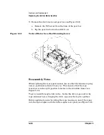
The following steps explain proper mounting of the frame.
1. Place the frame back in the chassis. Let it rest on its support points.
The rear of the frame rests on a ledge on the vertical motor.
2. Pull the tensioners down so that they are next to their mount points
on the sides and rear of the translate frame. Press them into the side
of the translate frame.
3. While tightening the mounting screw in a tensioner, push down on
the frame at that point to make sure that the translate frame remains
on its lower stop while you tighten the mounting screw.
4. Check that the translate frame is mounted level on the cables by
centering the picker and pushing the frame down lightly and quickly.
If you hear a “click” it means that the frame has slack and needs
adjustment.
If adjustment is necessary, remount the frame on the tensioners as
described in Step 3 and retest.
Figure 5-27
Remounting the Tensioners on the Translate Frame
Mounting the Vertical Encoder Strip
Summary of Contents for Surestore 160ex - Optical Jukebox
Page 10: ...TOC x Contents ...
Page 14: ...Tables TOC xiv ...
Page 15: ...Chapter 1 1 1 Product Information 1 Product Information ...
Page 26: ...Product Information Environmental Specifications Chapter 1 1 12 ...
Page 27: ...Chapter 2 2 1 Installation 2 Installation ...
Page 30: ...Installation Identifying Controls and Features Chapter 2 2 4 Figure 2 2 Left Side ...
Page 47: ...Chapter 3 3 1 Operation and Configuration 3 Operation and Configuration ...
Page 75: ...Chapter 4 4 1 Troubleshooting and Diagnostics 4 Troubleshooting and Diagnostics ...
Page 122: ...Troubleshooting and Diagnostics Running an Internal Test Chapter 4 4 48 ...
Page 123: ...Chapter 5 5 1 Removal and Replacement 5 Removal and Replacement ...
Page 129: ...Removal and Replacement Service Access Chapter 5 5 7 Removal and Replacement Front Panel ...
Page 188: ...Removal and Replacement Replaceable Parts Chapter 5 5 66 Figure 5 43 Exploded View 1 of 3 ...
Page 190: ...Removal and Replacement Replaceable Parts Chapter 5 5 68 Figure 5 45 Exploded View 3 of 3 ...
Page 192: ...Removal and Replacement Replaceable Parts Chapter 5 5 70 Figure 5 47 Rope and Pulley System ...
Page 193: ...Chapter 6 6 1 Theory of Operation 6 Theory of Operation ...
Page 218: ...Theory of Operation Optical Drive Mechanism Chapter 6 6 26 ...
Page 219: ...Appendix A A 1 Safety and Regulatory A Safety and Regulatory Information ...


