Removal and Replacement
Replaceable Parts
Chapter 5
5-62
Replaceable Parts
NOTE
The “x” in the part numbers listed in the following parts tables
represents a number from “0” to “9” depending on the revision of the
part. For example, if the part is newly released, the number will be “0”.
The first time the part is revised, the number increments to “1”; the
second time the part is revised, the number increments to“2”, and so on.
If you are unsure of the current part number, enter a “0” or a “1” in place of the “x” when
checking your parts database and the current part number will display.
Table 5-2
Exchange Parts
FRU No.
Part Number
Description
2
C1113-69x14
optical drive mechanism, 9.1-Gb
2
C1113-69x08
optical drive mechanism, 5.2-Gb
19
C1170-69x03
configuration module
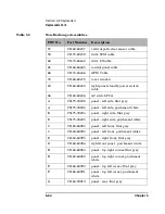
Table 5-3
Non-Exchange Assemblies
FRU No.
Part Number
Description
1
C1153-60x01
robotic controller PCA
2
C1113-60x14
optical drive mechanism, 9.1-Gb
2
C1113-60x08
optical drive mechanism, 5.2-Gb
4
C1150-60x04
interposer PCA
8
C1150-60x08
SCSI interface PCA
19
C1170-60x03
configuration module
22
C1160-60x22
display assembly
23
C1160-60x23
vertical motor gearbox assembly
24
C1160-60x24
vertical motion motor
Summary of Contents for Surestore 160ex - Optical Jukebox
Page 10: ...TOC x Contents ...
Page 14: ...Tables TOC xiv ...
Page 15: ...Chapter 1 1 1 Product Information 1 Product Information ...
Page 26: ...Product Information Environmental Specifications Chapter 1 1 12 ...
Page 27: ...Chapter 2 2 1 Installation 2 Installation ...
Page 30: ...Installation Identifying Controls and Features Chapter 2 2 4 Figure 2 2 Left Side ...
Page 47: ...Chapter 3 3 1 Operation and Configuration 3 Operation and Configuration ...
Page 75: ...Chapter 4 4 1 Troubleshooting and Diagnostics 4 Troubleshooting and Diagnostics ...
Page 122: ...Troubleshooting and Diagnostics Running an Internal Test Chapter 4 4 48 ...
Page 123: ...Chapter 5 5 1 Removal and Replacement 5 Removal and Replacement ...
Page 129: ...Removal and Replacement Service Access Chapter 5 5 7 Removal and Replacement Front Panel ...
Page 188: ...Removal and Replacement Replaceable Parts Chapter 5 5 66 Figure 5 43 Exploded View 1 of 3 ...
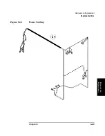
Page 190: ...Removal and Replacement Replaceable Parts Chapter 5 5 68 Figure 5 45 Exploded View 3 of 3 ...
Page 192: ...Removal and Replacement Replaceable Parts Chapter 5 5 70 Figure 5 47 Rope and Pulley System ...
Page 193: ...Chapter 6 6 1 Theory of Operation 6 Theory of Operation ...
Page 218: ...Theory of Operation Optical Drive Mechanism Chapter 6 6 26 ...
Page 219: ...Appendix A A 1 Safety and Regulatory A Safety and Regulatory Information ...

