


Theory of Operation
Optical Drive Mechanism
Chapter 6
6-23
T
h
eory
o
f Operat
io
n
the cartridge shuttle to raise and lower the cartridge within the loader
housing.
Bias Magnet
The bias magnet subassembly sits on top of the cartridge shuttle and
provides the correct polarity for erasing or writing data.
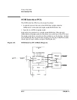
Optical Head
The optical head assembly contains both mechanical and electronic
components and is a “split optics” design, which physically separates the
laser diode.
The actuators and laser diode (and associated detectors) are on a small
PCA on the optical head assembly. The main components are as follows:
• Auto Laser Power Control (ALPC): Controls the intensity and
duration of the laser beam for erase, write, and read operations.
• Focus Servo (Fcs): Controls the vertical motion of the objective lens to
focus the laser beam on the disk surface.
• Fine Tracking Servo (Trk): Controls the horizontal motion of the
objective lens to follow the track of the disk.
• Linear Motor (LM): Positions the actuator in the vicinity of the
desired track on the disk.
Errors
The various error thresholds are the basis for deciding whether or not to
spare a sector. This could happen during the certification process (i.e. the
slip sparing algorithm) or auto-reallocation during a SCSI Write
command (i.e. the replacement sparing algorithm). These error
thresholds are related to the format of a sector in the User Zone.
Each sector in the User Zone consists of the following:
• Header
• User data
• Parity bytes for error correction
Each header consists of three copies of the sector's track number, sector
Summary of Contents for Surestore 160ex - Optical Jukebox
Page 10: ...TOC x Contents ...
Page 14: ...Tables TOC xiv ...
Page 15: ...Chapter 1 1 1 Product Information 1 Product Information ...
Page 26: ...Product Information Environmental Specifications Chapter 1 1 12 ...
Page 27: ...Chapter 2 2 1 Installation 2 Installation ...
Page 30: ...Installation Identifying Controls and Features Chapter 2 2 4 Figure 2 2 Left Side ...
Page 47: ...Chapter 3 3 1 Operation and Configuration 3 Operation and Configuration ...
Page 75: ...Chapter 4 4 1 Troubleshooting and Diagnostics 4 Troubleshooting and Diagnostics ...
Page 122: ...Troubleshooting and Diagnostics Running an Internal Test Chapter 4 4 48 ...
Page 123: ...Chapter 5 5 1 Removal and Replacement 5 Removal and Replacement ...
Page 129: ...Removal and Replacement Service Access Chapter 5 5 7 Removal and Replacement Front Panel ...
Page 188: ...Removal and Replacement Replaceable Parts Chapter 5 5 66 Figure 5 43 Exploded View 1 of 3 ...
Page 190: ...Removal and Replacement Replaceable Parts Chapter 5 5 68 Figure 5 45 Exploded View 3 of 3 ...
Page 192: ...Removal and Replacement Replaceable Parts Chapter 5 5 70 Figure 5 47 Rope and Pulley System ...
Page 193: ...Chapter 6 6 1 Theory of Operation 6 Theory of Operation ...
Page 218: ...Theory of Operation Optical Drive Mechanism Chapter 6 6 26 ...
Page 219: ...Appendix A A 1 Safety and Regulatory A Safety and Regulatory Information ...


