Hardware options installation 80
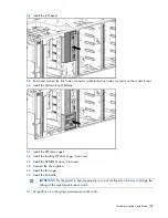
For more information, see the documentation that ships with the expander card.
9.
Install the fan cage.
10.
Install the air baffle.
11.
Install the access panel.
12.
Do one of the following:
o
Close or install the tower bezel, as needed.
o
Slide the server back into the rack.
13.
Power up the server (on page
22
).
Graphics adapter option
The server supports up to three high-power graphics adapters.
Install graphics adapters in the x16 PCIe expansion slots. For more information, see "System board
components (on page
13
)."
Before installing a high-power graphics adapter in the server, be sure that the power supplies support the
installation of the adapter. Due the high power requirements for the adapter, a 750W or higher power
supply may be required. For more information, see the HP Enterprise Configurator website
(
http://h30099.www3.hp.com/configurator/
).
To install the component:
1.
Power down the server (on page
22
).
2.
Do one of the following:
o
Open or remove the tower bezel, as needed ("
Open or remove the tower bezel
" on page
22
).
o
Extend the server from the rack (on page
24
).
3.
Remove the access panel (on page
25
).
4.
Remove the air baffle (on page
26
).
5.
Remove the fan cage (on page
26
).
6.
Install the graphics adapter in a x16 PCIe expansion slot.
7.
Connect the power cables.
For more information, see the documentation that ships with the graphics adapter power cable kit.
8.
Install the fan cage.
9.
Install the air baffle.
10.
Install the access panel.
11.
Do one of the following:
o
Close or install the tower bezel, as needed.
o
Slide the server back into the rack.
12.
Power up the server (on page
22
).
Tower-to-rack conversion kit option
The tower-to-rack conversion kit includes all equipment required to convert the tower model server into a
rack model server and to install the server into most square- or round-hole racks.
Summary of Contents for ProLiant DL370
Page 1: ...HP ProLiant DL ML370 G6 Server User Guide Part Number 513482 001 March 2009 First Edition ...
Page 16: ...Component identification 16 SFF hard drives LFF hard drives ...
Page 29: ...Operations 29 6 Remove the hard drive cage blank ...
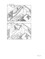
Page 94: ...Cabling 94 Drive cage bay 2 Drive cage bay 3 ...
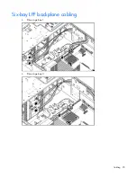
Page 95: ...Cabling 95 Six bay LFF backplane cabling Drive cage bay 1 Drive cage bay 2 ...
Page 97: ...Cabling 97 Battery cabling for BBWC DVD ROM drive cabling ...
Page 98: ...Cabling 98 Slimline optical drive cabling ...
Page 123: ...Troubleshooting 123 ...
Page 146: ...Technical support 146 ...
Page 147: ...Technical support 147 ...


