Chapter 6
6-5
System Servicing
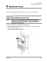
Removing the System for Servicing
System Replacement
1. Extend the cabinet base assembly fully forward.
2. Position the system onto the base assembly as shown in Figure 6-4, aligning and setting
the system onto the guide pins (callout (1)) in the base plate assembly.
CAUTION
The system weighs as much as 100 lbs and may cause strain if lifted by one
person. Use two people to lift and align the system.
3. Secure the fixed support bracket with the eight screws as shown in callout (2) of Figure
6-3.
4. Secure the pivot support bracket with the three screws as shown in callout (1) of Figure
6-3.
5. Replace the three screws along the rear of the assembly (refer to Figure 6-4).
6. Attach any new (or previously detached) cables to the system.
NOTE
Attaching the cables while the rails are extended fully forward will ensure
sufficient slack for later maintenance.
CAUTION
If the power supply was changed, ensure that the voltage setting of the switch
on the power supply matches the voltage of the cabinet PDU or UPS, if
present.
Summary of Contents for A1896A
Page 10: ...1 4 Chapter1 Introduction Required Tools ...
Page 24: ...4 4 Chapter4 Cabinet Operation Turning Off the Computer System With UPS ...
Page 26: ...5 2 Chapter5 Removal and Replacement Procedures Figure 5 2 Cabinet Exploded View Rear ...
Page 36: ...5 12 Chapter5 Removal and Replacement Procedures Removal and Replacement Procedures ...
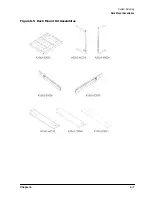
Page 43: ...Chapter 6 6 7 System Servicing Rack Mount Assemblies Figure 6 5 Rack Mount Kit Assemblies ...
Page 44: ...6 8 Chapter6 System Servicing Rack Mount Assemblies ...


