5-4
Chapter 5
Removal and Replacement Procedures
Removal and Replacement Procedures
Removal and Replacement Procedures
The following procedures are for the HP Field Replaceable Units (FRUs) contained in the
HP A1896A or HP A1897A rack-mount cabinets.
Rear Door
Refer to Figure 5-1 while performing these procedures.
Rear Door Removal:
1. Remove the rear door of the cabinet by opening the door.
2. Disconnect the bonding wire from the door.
3. Grasp the rear door support and lift the door straight up and away from the cabinet.
Rear Door Replacement:
1. Hold the rear door by the support column, in an open position.
2. Align the door hinge pins over the cabinet hinge holes.
3. Lower the door onto the cabinet hinge.
4. Reconnect the bonding wire to the door.
Top Cap
Refer to Figure 5-1 while performing these procedures.
Top Cap Removal:
1. Turn the cabinet power switch off and unplug the cabinet power cord.
2. Open the rear door all the way.
3. Remove the two outside mounting screws at the top rear of the cabinet.
4. From the rear of the cabinet, pull the top cap toward the back a few inches.
5. Lift the top cap off the cabinet.
Top Cap Replacement:
1. Ballast assembly is not provided on all configurations
8120-5470
Rack device Power cord, 20 inches
8120-1396
Rack device power cord, 30 inches
C2786-00036
No.
Part No.
Description
Summary of Contents for A1896A
Page 10: ...1 4 Chapter1 Introduction Required Tools ...
Page 24: ...4 4 Chapter4 Cabinet Operation Turning Off the Computer System With UPS ...
Page 26: ...5 2 Chapter5 Removal and Replacement Procedures Figure 5 2 Cabinet Exploded View Rear ...
Page 36: ...5 12 Chapter5 Removal and Replacement Procedures Removal and Replacement Procedures ...
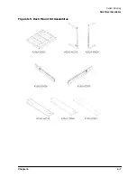
Page 43: ...Chapter 6 6 7 System Servicing Rack Mount Assemblies Figure 6 5 Rack Mount Kit Assemblies ...
Page 44: ...6 8 Chapter6 System Servicing Rack Mount Assemblies ...

