3-6
Chapter 3
Unpacking and Installation
Cabinet Inspection
Cabinet Inspection
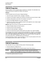
Once the cabinet is off the shipping pallet, and before it is placed in the installation site,
inspect the internal and external condition of the cabinet.
Exterior:
Check the cabinet exterior for signs of shipping damage:
1. Look at the top and sides for dents, warpage, or scratches.
2. Check the front bezels for alignment, scratches, and that they open and close normally.
3. Check any filler panels on the front of the cabinet, for proper fit.
4. Check the forehead assembly for any signs of damage.
5. Check the rear door for dents, scratches, proper fit, and operation. Also visually inspect
the fit of the door when it is closed.
Interior: Open the rear door and inspect the inside of the cabinet.
1. Inspect all cables, make sure they are secure.
2. Inspect all rails for signs of damage.
3. Check all mounting screws for tightness.
4. Check all components for signs of shifting during shipment or any signs of damage.
If any damage is found, follow the claims procedures described in Chapter 1. Some damage
may be repaired by replacing a damaged part, if that part is replaceable. Refer to Chapter
5 for a list of field replaceable parts for the cabinet. For internal component damage, refer
to the Service Manual for replaceable parts and procedures.
If extensive damage is found, it may be necessary to return the entire cabinet to HP. Refer
to the Repacking instructions listed in this chapter.
Cabinet Installation
The installation of the pre-loaded cabinets consist of the following steps:
1. Move the cabinet to installation site.
2. Lower the leveling feet. (This will prevent excessive wear on the casters.)
CAUTION
It is strongly urged that the cabinet stabilizers also be extended as an
additional safeguard against overturning the cabinet during installation. The
stabilizer is an extendable slide located at the bottom front of the cabinet.
3. Connect the system console to the server.
Summary of Contents for A1896A
Page 10: ...1 4 Chapter1 Introduction Required Tools ...
Page 24: ...4 4 Chapter4 Cabinet Operation Turning Off the Computer System With UPS ...
Page 26: ...5 2 Chapter5 Removal and Replacement Procedures Figure 5 2 Cabinet Exploded View Rear ...
Page 36: ...5 12 Chapter5 Removal and Replacement Procedures Removal and Replacement Procedures ...
Page 43: ...Chapter 6 6 7 System Servicing Rack Mount Assemblies Figure 6 5 Rack Mount Kit Assemblies ...
Page 44: ...6 8 Chapter6 System Servicing Rack Mount Assemblies ...

