6-2
Chapter 6
System Servicing
Preparing the System for Servicing
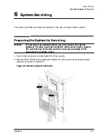
3. Remove the three screws on each side of the support brackets which attach the bracket
to the cabinet frame (refer to callout (1) in Figure 6-2).
4. Grasp the system just below the front center of the support brackets and pull toward
you, extending the system fully forward on its rails.
5. Using a T15 TORX screwdriver, remove the three screws in the pivot support bracket
(refer to callout (2) in Figure 6-2).
6. Swing the pivot support bracket around to the right and secure it by pressing it against
the fixed support bracket. The pivot support bracket will click into place.
Figure 6-2 Opening the pivot support bracket.
7. To access the interior of the system for service, refer to the System Service Manual, part
number A3262-90011.
Summary of Contents for A1896A
Page 10: ...1 4 Chapter1 Introduction Required Tools ...
Page 24: ...4 4 Chapter4 Cabinet Operation Turning Off the Computer System With UPS ...
Page 26: ...5 2 Chapter5 Removal and Replacement Procedures Figure 5 2 Cabinet Exploded View Rear ...
Page 36: ...5 12 Chapter5 Removal and Replacement Procedures Removal and Replacement Procedures ...
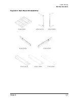
Page 43: ...Chapter 6 6 7 System Servicing Rack Mount Assemblies Figure 6 5 Rack Mount Kit Assemblies ...
Page 44: ...6 8 Chapter6 System Servicing Rack Mount Assemblies ...


