Chapter 5
5-7
Removal and Replacement Procedures
Removal and Replacement Procedures
Fan Assembly
Refer to Figure 5-3 and Figure 5-2 while performing these procedures.
NOTE
The fan assembly is not present in the 1.1 meter cabinet.
Fan Assembly Removal:
1. Turn off the cabinet power. Refer to the power off procedures in Chapter 5.
2. Open the rear door.
3. disconnect the fan power cord from the PDU.
4. Remove the one mounting screw at the top rear cabinet frame bar.
5. Grasp the fan assembly from the bottom and pull toward the rear of the cabinet.
6. The fan assembly should release from the cabinet, and can be lowered out of the
cabinet.
Fan Assembly Replacement:
1. Raise the fan assembly into the rear cabinet frame opening.
2. Slide the fan assembly forward engaging the tabs on the fan assembly into the slots in
the cabinet frame.
3. Insert the mounting screw. Tighten the screw.
4. Connect the fan power cord from the fan assembly to the PDU.
5. The rear door can now be closed and the system powered up.
Figure 5-3 Fan Assembly
Summary of Contents for A1896A
Page 10: ...1 4 Chapter1 Introduction Required Tools ...
Page 24: ...4 4 Chapter4 Cabinet Operation Turning Off the Computer System With UPS ...
Page 26: ...5 2 Chapter5 Removal and Replacement Procedures Figure 5 2 Cabinet Exploded View Rear ...
Page 36: ...5 12 Chapter5 Removal and Replacement Procedures Removal and Replacement Procedures ...
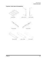
Page 43: ...Chapter 6 6 7 System Servicing Rack Mount Assemblies Figure 6 5 Rack Mount Kit Assemblies ...
Page 44: ...6 8 Chapter6 System Servicing Rack Mount Assemblies ...


