Tables
vi
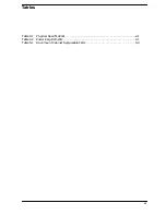
Table 2-1 Physical Specifications . . . . . . . . . . . . . . . . . . . . . . . . . . . . . . . . . . . . . . . . . . . . . .2-1
Table 2-2 Power Requirements . . . . . . . . . . . . . . . . . . . . . . . . . . . . . . . . . . . . . . . . . . . . . . . .2-1
Table 5-1 Rack-mount Cabinet Replaceable Parts. . . . . . . . . . . . . . . . . . . . . . . . . . . . . . . . .5-3
Summary of Contents for A1896A
Page 10: ...1 4 Chapter1 Introduction Required Tools ...
Page 24: ...4 4 Chapter4 Cabinet Operation Turning Off the Computer System With UPS ...
Page 26: ...5 2 Chapter5 Removal and Replacement Procedures Figure 5 2 Cabinet Exploded View Rear ...
Page 36: ...5 12 Chapter5 Removal and Replacement Procedures Removal and Replacement Procedures ...
Page 43: ...Chapter 6 6 7 System Servicing Rack Mount Assemblies Figure 6 5 Rack Mount Kit Assemblies ...
Page 44: ...6 8 Chapter6 System Servicing Rack Mount Assemblies ...

