6-4
Chapter 6
System Servicing
Removing the System for Servicing
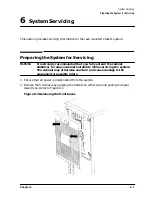
4. Remove the three screws connecting the rear of the base plate assembly to the rear of
the component chassis (see Figure 6-4).
Figure 6-4 Positioning the System
5. Lift and remove the system from the base assembly.
CAUTION
The system weighs as much as 100 lbs and may cause strain if lifted by one
person. Use two people to lift and remove the system.
6. Perform additional servicing as required.
7. Replace the system in the cabinet (see “System Replacement”).
Summary of Contents for A1896A
Page 10: ...1 4 Chapter1 Introduction Required Tools ...
Page 24: ...4 4 Chapter4 Cabinet Operation Turning Off the Computer System With UPS ...
Page 26: ...5 2 Chapter5 Removal and Replacement Procedures Figure 5 2 Cabinet Exploded View Rear ...
Page 36: ...5 12 Chapter5 Removal and Replacement Procedures Removal and Replacement Procedures ...
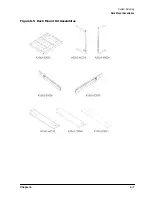
Page 43: ...Chapter 6 6 7 System Servicing Rack Mount Assemblies Figure 6 5 Rack Mount Kit Assemblies ...
Page 44: ...6 8 Chapter6 System Servicing Rack Mount Assemblies ...


