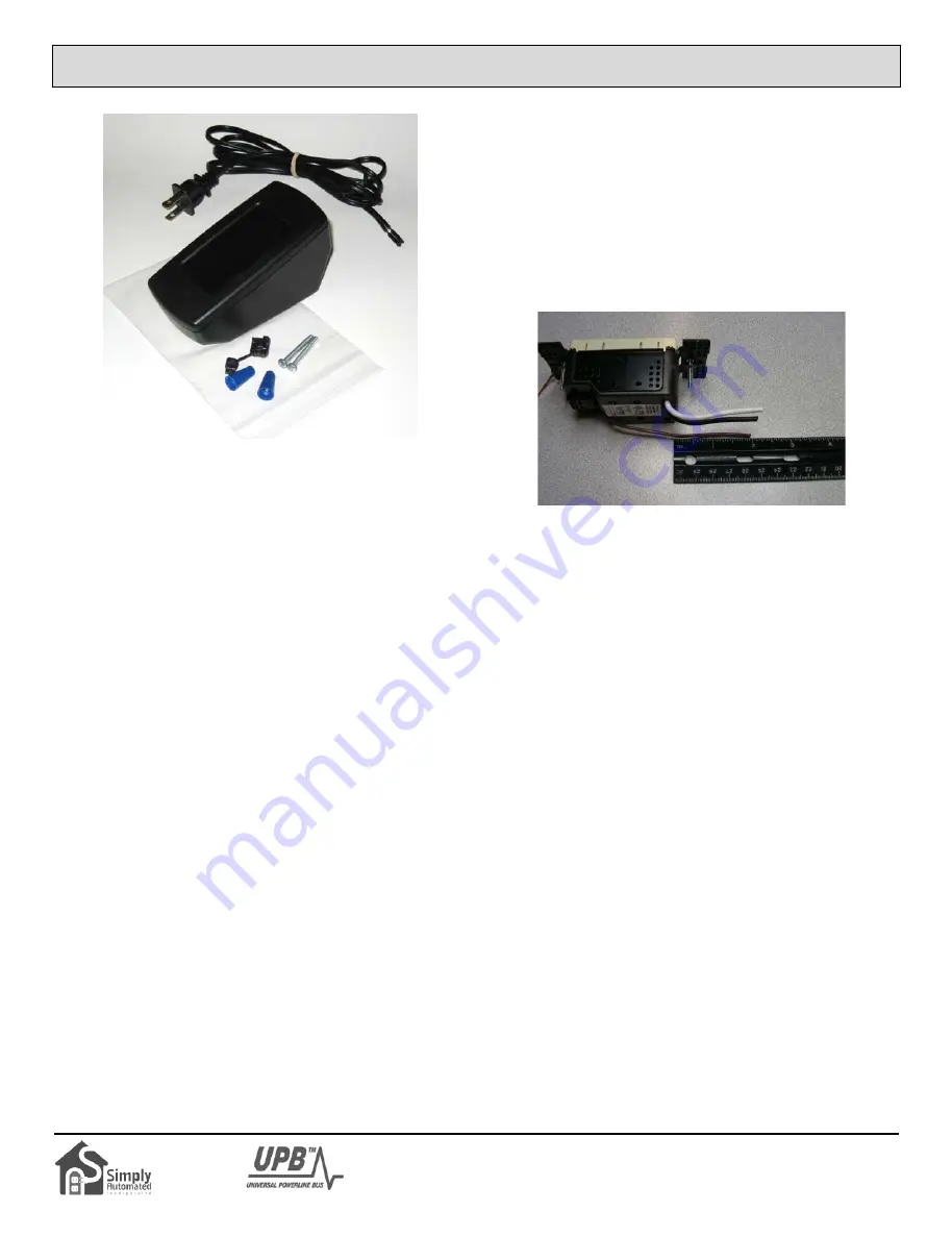
Tabletop Pedestal Enclosure
Model ZTP2
FUNCTION
The Tabletop Pedestal Enclosure, model ZTP2, is used to table
mount a Simply Automated, model US2, Universal Dimming
Transceiver Base and any of the matching, multi- rocker or push-
button faceplates. With the ZTP2, a qualified technician can wire
in a quad-rocker switch or even an 8-button controller. Once
assembled, the Tabletop controller can be configured to activate
other UPB devices, such as lamp modules, dimming switches and
UPB lighting scenes.
The Tabletop Pedestal can be located anywhere in the home.
They are conveniently used on a bedside nightstand, on the desk
in a home office or next to the favorite TV recliner. No additional
wiring is required and no radio frequency signals are used.
IMPORTANT SAFETY INSTRUCTIONS
When using electrical products, basic safety precautions should
always be followed, including the following:
1. READ AND FOLLOW ALL SAFETY INSTRUCTIONS.
2. Installation should be performed by a qualified electrician.
3. Keep away from water. If product comes into contact with
water or other liquid, unplug immediately.
4. Never use products that have been dropped or damaged.
5. Do not use this product outdoors.
6. Do not use this product for other than its intended use.
7. To avoid risk of fire, burns, personal injury and electric shock,
install this product out of reach of small children.
8. Do not cover the product with cloth, paper or any material
when in use.
9. This product uses polarized plugs and sockets (one blade is
wider than the other) as a feature to reduce the risk of
electric shock. These plugs and sockets fit only one way. If
they do not fit, contact a qualified technician. Do not use with
an extension cord unless plugs can be fully inserted. Do not
alter or replace plugs.
10. SAVE THESE INSTRUCTIONS.
INSTALLATION
The Tabletop Pedestal is designed for indoor use.
1. Check to make sure all ZTP2 parts are available: enclosure
lid and base, 2 enclosure screws (6/32 x 1 ¼ inch), 3 wire
nuts, power cord, and a strain relief grommet. US2
transceiver and faceplate are sold separately.
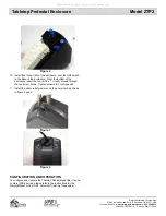
2. To prepare the US2 transceiver first cut off ground wire, then
bend remaining wires toward the top of the transceiver and
cut the wires approximately 2 inches above the transceiver
body, as shown in figure 1.
Figure 1
3. Strip back US2 wires (0.375 inches), as indicated on the strip
gauge located on back of the US2-40. Install a wire nut on
the brown wire to prevent this un-used wire from shorting or
causing shock.
4. Remove the two (6/32 x ¾ inch) mounting screws and
retainers from the US2 transceiver. These two screws and
retainer will not be needed.
5. Install the rocker or button faceplate of choice on the front of
the US2 transceiver as described in the US2 installation
instructions.
6. Thread the stripped wire end of the power cord through the
hole in the base of the pedestal so that approximately 6
inches of the power cord wires are available from inside the
base of the enclosure.
7. From the two wires of the power cord inside the base
enclosure, locate the ribbed neutral wire. Note the ribbed
neutral wire is connected to the large blade on the plug of the
power cord. Using a wire nut, connect this ribbed neutral
wire of the power cord to the white wire of the US2
transceiver.
8. Using a wire nut connect the non-ribbed power cord wire to
the black wire of the US2 transceiver.
9. Install the US2 transceiver in the enclosure base so that the
wire nuts are tucked into the large end of the base; above the
power cord hole and below the top mounting bracket of the
US2 transceiver, see figure 2.
Continued on Page 2
Simply Automated, Incorporated
6108 Avenida Encinas, Suite B, Carlsbad, CA 92011 USA
Technical Support:
www.simply-automated.com
or
800-630-9234
452-0008-1001 Rev. B Revised: May 27, 2008
All manuals and user guides at all-guides.com
all-guides.com


