background image

5

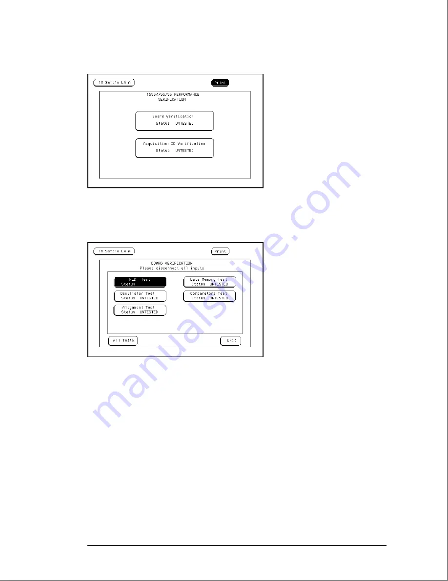
In the Performance Verification menu, touch the field labeled Board Verification.

6

In the Board Verification menu, touch All Tests.

You can run all tests at one time by touching All Tests.  To see more details about each test
when troubleshooting failures, you can run each test individually.  This example shows how to
run all tests at once.

7

When the tests finish, the status will show Passed or Failed.  Record the results of
the Board Verification tests in the performance test record at the end of this chapter.

Testing Performance

To perform the self-tests and make the test connectors

3–4

Summary of Contents for 16555A

Page 1: ... First edition October 1996 For Safety information Warranties and Regulatory information see the pages at the end of the book Copyright Hewlett Packard Company 1987 1996 All Rights Reserved HP 16555A D 110 MHz State 500 MHz Timing Logic Analyzers ...

Page 2: ...sales and service contact information in this manual may be out of date The latest service and contact information for your location can be found on the Web at http www agilent com find assist If you do not have access to the Internet contact your field engineer or the nearest sales and service office listed below In any correspondence or telephone conversation refer to your instrument by its mode...

Page 3: ...mory depth per channel for the HP 16555A 2032K memory depth per channel for the HP 16555D 110 MHz maximum state acquisition speed 500 MHz maximum timing acquisition speed Expandable to 204 channels Service Strategy The service strategy for this instrument is the replacement of defective assemblies This service guide contains information for finding a defective assembly by testing and servicing the...

Page 4: ...The HP 16555A D Logic Analyzer iii ...

Page 5: ... characteristics of the module and a list of the equipment required for servicing the module Chapter 2 tells how to prepare the module for use Chapter 3 gives instructions on how to test the performance of the module Chapter 4 contains calibration instructions for the module Chapter 5 contains self tests and flowcharts for troubleshooting the module Chapter 6 tells how to replace the module and as...

Page 6: ...acy 3 9 To test the single clock single edge state acquisition 3 18 To test the multiple clock multiple edge state acquisition 3 30 To test the single clock multiple edge state acquisition 3 41 To test the time interval accuracy 3 51 To perform the multicard test 3 57 Performance Test Record 3 67 4 Calibrating 5 Troubleshooting To use the flowcharts 5 2 To run the self tests 5 7 To run the Board V...

Page 7: ...7 Replaceable Parts Replaceable Parts Ordering 7 2 Replaceable Parts List 7 3 Exploded View 7 5 8 Theory of Operation Block Level Theory 8 2 Self Tests Description 8 6 Contents vi ...

Page 8: ...1 Accessories 1 2 Operating System 1 2 Specifications 1 3 Characteristics 1 4 Supplemental Characteristics 1 4 Recommended Test Equipment 1 7 General Information ...

Page 9: ...500B Mainframe The HP 16555D Logic Analyzer requires operating system version v3 10 or higher For the HP 16555A the version of the operating system software depends on the programmable logic device that is the CPU interface To verify the version of the programmable device first locate the device which is at the front of the HP 16555A board If the programmable device has part number 16555 80001 the...

Page 10: ...0 ns Multiple Clocks Multiple Edges Setup Hold Time 1 0 0 4 5 ns through 4 5 0 0 ns adjustable in 500 ps increments Maximum State Speed 100 MHz Minimum Master to Master Clock Time 1 10 0 ns 1 Specified for an input signal VH 0 9 V VL 1 7 V and threshold 1 3 V 2 An HP 16555A in an HP 16500B mainframe using operating system v2 xx has maximum state speed of 100 MHz and minimum Master to Master Clock ...

Page 11: ...ce 100 kΩ 2 Input Capacitance 8 pF Minimum Voltage Swing 500 mV peak to peak Maximum Input Voltage 40 V CAT I Threshold Range 6 0 V adjustable in 50 mV increments Clock In Out Clock Output 850 mV 100 MHz terminated into 50 Ω Clock Input 1 0 V 100 MHz 20 Vdc offset clock input port is terminated internally to 50 Ω State Analysis State Clock Qualifiers 4 Time Tag Resolution 8 ns Maximum Time Count B...

Page 12: ...nes maximum with scrolling across 96 waveforms Measurement Functions Run Stop Functions Run Starts acquisition of data in specified trace mode Stop In single trace mode or the first run of a repetitive acquisition STOP halts acquisition and displays the current acquisition data For subsequent runs in repetitive mode STOP halts acquisition of data and does not change the current display Trace Mode ...

Page 13: ...d trigger or between two states Patterns The X and 0 markers can be used to locate the nth occurrence of a specified pattern from trigger or from the beginning of data The 0 marker can also find the nth occurrence of a pattern from the X marker Statistics X and 0 marker statistics are calculated for repetitive acquisitions Patterns must be specified for both markers and statistics are kept only wh...

Page 14: ...ion 0 005 accuracy HP 3458A P BNC Banana Cable HP 11001 60001 P BNC Tee BNC m f f HP 1250 0781 P Cable BNC m m 48 inch HP 10503A P SMA Coax Cable Qty 3 18 GHz bandwidth HP 8120 4948 P BNC Coax Cable BNC m m 2 GHz bandwidth HP 8120 1840 P Adapter Qty 4 SMA m BNC f HP 1250 1200 P Adapter SMA f BNC m HP 1250 2015 P Coupler BNC m m HP 1250 0216 P 20 1 Probes Qty 2 HP 54006A P BNC Test Connector 17x2 Q...

Page 15: ...1 8 ...

Page 16: ... 2 To prepare the mainframe 2 3 To configure a one card module 2 4 To configure a multicard module 2 5 To install the module 2 10 To turn on the system 2 11 To test the module 2 11 To install the ferrites 2 12 Preparing for Use ...

Page 17: ...densing Storage Store or ship the logic analyzer in environments within the following limits Temperature 40 C to 75 C Humidity Up to 90 at 65 C Altitude Up to 15 300 meters 50 000 feet Protect the module from temperature extremes which cause condensation on the instrument To inspect the module 1 Inspect the shipping container for damage If the shipping container or cushioning material is damaged k...

Page 18: ...ow the slots intended for installation do not have to be removed Starting from the top loosen the thumb screws on filler panels and cards that need to be moved 4 Starting from the top pull the cards and filler panels that need to be moved halfway out C AU TI O N All multicard modules will be cabled together Pull these cards out together 5 Remove the cards and filler panels Remove the cards or fill...

Page 19: ...ctor labeled Master J6 on each card see figure below C AU TI O N If you pull on the flexible ribbon part of the 2x10 cable you might damage the cable assembly Using your thumb and finger grasp the ends of the cable connector Apply pressure to the ends of the cable connector to disengage the metal locking tabs of the connector from the cable socket on the board Then pull the connector from the cabl...

Page 20: ...combine HP 16555A cards and HP 16555D cards together in a multicard module A multicard module with both HP 16555A and HP 16555D cards will not operate 2 Obtain two 2x25 cables from the accessory pouch that match the number of expanders being configured The illustration shows the cables that are available and which cable is used in each expander configuration Preparing for Use To configure a multic...

Page 21: ... card J10 4 On the expander cards disconnect the end of the 2x10 cable that is plugged into the connector labeled Master C AU TI O N If you pull on the flexible ribbon part of the 2x10 cable you might damage the cable assembly Using your thumb and finger grasp the ends of the cable connector Apply pressure to the ends of the cable connector to disengage the metal locking tabs of the connector from...

Page 22: ... Plug the 2x25 cables into J9 and J10 of the expander card 6 Feed the free end of the 2x10 cable of the expander cards through the access holes to the master card Plug the 2x10 cable into J5 on the master card Preparing for Use To configure a multicard module 2 7 ...

Page 23: ...card through the cable access holes of the expander card Plug the 2x25 cables into J9 and J10 of the expander card 8 Feed the free end of the 2x10 cables of the expander cards through the access holes to the master card Plug the 2x10 cable into J7 on the master card Preparing for Use To configure a multicard module 2 8 ...

Page 24: ...on of the 2x25 cables and the 2x10 cables for a three card module A two card module is configured in the same manner with the expansion card above the master card Make sure ALL cables are firmly seated Preparing for Use To configure a multicard module 2 9 ...

Page 25: ...so that the endplates overlap 5 Seat the cards and tighten the thumbscrews Starting with the bottom card firmly seat the cards into the backplane connector of the mainframe Keep applying pressure to the center of the card endplate while tightening the thumbscrews finger tight Repeat this for all cards and filler panels starting at the bottom and moving to the top C AU TI O N Correct air circulatio...

Page 26: ...r The HP 16555D will appear as 2 0M SAMPLE 110 500MHz LA To test the module The logic analyzer module does not require an operational accuracy calibration or adjustment After installing the module you can test and use the module If you require a test to verify the specifications start at the beginning of chapter 3 Testing Performance If you require a test to initially accept the operation perform ...

Page 27: ... to absorb radio frequency energy Adding or removing the ferrite will not affect the normal operation of the analyzer 1 Place the ferrite halves on the logic analyzer cable like a clamshell around the whole cable The ferrite should be no more than 15 cm about 6 in from the rear panel of the logic analyzer 2 Insert the clamps onto the ends of the ferrites The locking tab should fit cleanly in the f...

Page 28: ...t the single clock single edge state acquisition 3 18 To test the multiple clock multiple edge state acquisition 3 30 To test the single clock multiple edge state acquisition 3 41 To test the time interval accuracy 3 51 To perform the multicard test 3 57 Performance Test Record 3 67 Testing Performance ...

Page 29: ...ard module from the mainframe and configure each card as a one card module Install the one card modules into the mainframe and perform the one card manual performance tests on each card When the tests are complete remove the one card modules reconfigure them into a multicard module reinstall the module into the mainframe then perform the final multi card test For removal instructions see chapter 6...

Page 30: ... test all at once The test connectors connect the analyzer to the test equipment Perform the self tests 1 Disconnect all inputs 2 In the System Configuration menu touch Configuration In the pop up touch Test 3 Touch the box labeled Touch Box to Load Test System 4 On the test system screen touch Test System Select the module to be tested For an HP 16555A select 1M Sample LA as the module to be test...

Page 31: ...e more details about each test when troubleshooting failures you can run each test individually This example shows how to run all tests at once 7 When the tests finish the status will show Passed or Failed Record the results of the Board Verification tests in the performance test record at the end of this chapter Testing Performance To perform the self tests and make the test connectors 3 4 ...

Page 32: ... by touching All Tests To see more details about each test when troubleshooting failures you can run each test individually This example shows how to run all tests at once 10 When the tests finish the status will show Passed or Failed Record the results of the Acquisition IC Verification tests in the performance test record at the end of this chapter Testing Performance To perform the self tests a...

Page 33: ...ct the next card then repeat the test When all cards are tested touch 1M Sample LA or 2M Sample LA then select Test System 12 Touch Configuration then select Test In the Test menu touch the box labeled Touch box to Exit Test System Testing Performance To perform the self tests and make the test connectors 3 6 ...

Page 34: ...strip b Solder a jumper wire to all pins on the other side of the Berg strip c Solder two resistors to the Berg strip one at each end between the end pins d Solder the center of the BNC connector to the center pin of one row on the Berg strip e Solder the ground tab of the BNC connector to the center pin of the other row on the Berg strip f On two of the test connectors solder a 20 1 probe The pro...

Page 35: ...g strip b Solder a jumper wire to all pins on the other side of the Berg strip c Solder the center of the BNC connector to the center pin of one row on the Berg strip d Solder the ground tab of the BNC connector to the center pin of the other row on the Berg strip Testing Performance To perform the self tests and make the test connectors 3 8 ...

Page 36: ... Required Equipment Critical Specifications Recommended Model Part Digital Multimeter 0 1 mV resolution 0 005 accuracy HP 3458A Function Generator DC offset voltage 6 3 V HP 3325B Option 002 BNC Banana Cable HP 11001 60001 BNC Tee HP 1250 0781 BNC Cable HP 8120 1840 BNC Test Connector 17x2 Set up the equipment 1 Turn on the equipment required and the logic analyzer Let them warm up for 30 minutes ...

Page 37: ...d 4 field then select Unassigned Connect the logic analyzer 1 Using the 17 by 2 test connector BNC cable and probe tip assembly connect the data and clock channels of Pod 1 to one side of the BNC Tee 2 Using a BNC banana cable connect the voltmeter to the other side of the BNC Tee 3 Connect the BNC Tee to the Main Signal output of the function generator Pod 3 Pod 4 field Testing Performance To tes...

Page 38: ...the multimeter to verify the voltage The activity indicators for Pod 1 should show all data channels and the J clock channel at a logic high 3 Using the Modify down arrow on the function generator decrease offset voltage in 1 mV increments until all activity indicators for Pod 1 show the channels at a logic low Record the function generator voltage in the performance test record Testing Performanc...

Page 39: ...erator increase offset voltage in 1 mV increments until all activity indicators for Pod 1 show the channels at a logic high Record the function generator voltage in the performance test record Testing Performance To test the threshold accuracy 3 12 ...

Page 40: ...ify down arrow on the function generator decrease offset voltage in 1 mV increments until all activity indicators for Pod 1 show the channels are at a logic low Record the function generator voltage in the performance test record 4 Using the Modify up arrow on the function generator increase offset voltage in 1 mV increments until all activity indicators for Pod 1 show the channels are at a logic ...

Page 41: ...el at a logic high 3 Using the Modify down arrow on the function generator decrease offset voltage in 1 mV increments until all activity indicators for Pod 1 show the channels at a logic low Record the function generator voltage in the performance test record 4 Using the Modify up arrow on the function generator increase offset voltage in 1 mV increments until all activity indicators show the chan...

Page 42: ... a logic high 3 Using the Modify down arrow on the function generator decrease offset voltage in 1 mV increments until all activity indicators for Pod 1 show the channels at a logic low Record the function generator voltage in the performance test record 4 Using the Modify up arrow on the function generator increase offset voltage in 1 mV increments until all activity indicators for Pod 1 show the...

Page 43: ...at a logic high 3 Using the Modify down arrow on the function generator decrease offset voltage in 1 mV increments until all activity indicators for Pod 1 show the channels at a logic low Record the function generator voltage in the performance test record 4 Using the Modify up arrow on the function generator increase offset voltage in 1 mV increments until all activity indicators for Pod 1 show t...

Page 44: ... finished testing Pod 2 connect the data and clock channels of pod 3 In the logic analyzer Configuration menu unassign Pods 1 and 2 assign Pods 3 and 4 to Machine 1 Start with Test the TTL threshold on page 3 11 substituting Pod 3 for Pod 1 If you just finished testing Pod 3 connect the data and clock channels of Pod 4 Start with Test the TTL threshold on page 3 11 substituting Pod 4 for Pod 1 If ...

Page 45: ...m BNC f HP 1250 1200 SMA Coax Cable Qty 3 HP 8120 4948 Coupler Qty 3 BNC m m HP 1250 0216 BNC Test Connector 6x2 Qty 3 Set up the equipment 1 Turn on the equipment required and the logic analyzer Let them warm up for 30 minutes before beginning the test if you have not already done so 2 Set up the pulse generator according to the following table Pulse Generator Setup Channel 1 Channel 2 Period Del...

Page 46: ...00 V Alternate Scale Attenuation 20 00 1 Scale 200 mV div Offset 1 300 V Thresholds user defined Units Volts Upper 980 mV Middle 1 30 V Lower 1 62 V Set up the logic analyzer 1 Set up the Configuration menu a In the System Configuration menu touch System then select 1M Sample LA 2M Sample LA for HP 16555D b In the Configuration menu assign all pods to Machine 1 To assign the pods touch the pod fie...

Page 47: ...Hz 2M State for HP 16555D 110 MHz single clock state acquisition mode is not available with HP 16555A operating system v2 xx Refer to page 1 2 3 Set up the Trigger menu a Touch Format then select Trigger In the Trigger menu touch Modify Trigger then select Clear Trigger then select All b Touch the Count Off field In the Count menu touch Off In the pop up select Time then touch Done to exit c Touch...

Page 48: ...ct the O Marker field At the numeric keypad enter 55 Touch Done d Touch the Find X pattern occurrences field At the numeric keypad enter 2047 Touch Done e Touch the Find X pattern field The field should toggle to Find O pattern f Touch the Find O pattern occurrences field At the numeric keypad enter 2048 Touch Done Testing Performance To test the single clock single edge state acquisition 3 21 ...

Page 49: ...lloscope to the pulse generator Connect the Logic Analyzer to the Pulse Generator Connect to HP 8131A Channel 1 Output Connect to HP 8131A Channel 1 Output Connect to HP 8131A Channel 2 Output Pod 1 channel 3 Pod 2 channel 3 Pod 3 channel 3 Pod 4 channel 3 Pod 1 channel 11 Pod 2 channel 11 Pod 3 channel 11 Pod 4 channel 11 J clock K clock L clock M clock Testing Performance To test the single cloc...

Page 50: ...n the oscilloscope Timebase menu select Position Using the oscilloscope knob position the clock waveform so that the waveform is centered on the screen d On the oscilloscope select Shift width channel 2 then select Enter to display the clock signal pulse width width 2 e If the pulse width is outside the limits adjust the pulse generator channel 2 width until the pulse width is within limits Testin...

Page 51: ...erator Chan 2 Doub in 10 ps increments until one of the two periods measured is less than 9 05 ns If running operating system version HP 16555A operating system v2 xx measure a master to master clock time of 10 ns 3 Check the data pulse width Using the oscilloscope verify that the data pulse width is 3 480 ns 20 ps or 80 ps a In the oscilloscope Timebase menu select Scale 1 000 ns div b In the osc...

Page 52: ...field and select the setup hold combination to be tested for all pods The first time through this test select the top combination in the following table Setup Hold Combinations 3 5 0 0 ns 0 0 3 5 ns 1 5 2 0 ns d Touch Done to exit the setup hold combinations 2 Disable the pulse generator channel 2 COMP LED off Testing Performance To test the single clock single edge state acquisition 3 25 ...

Page 53: ...annel 1 Delay until the pulses are aligned according the the setup time of the setup hold combination selected 0 0 ps or 100 ps 4 Select the clock to be tested a In the Master Clock menu touch the clock field to be tested and then select the clock edge as indicated in the table The first time through this test select the first clock and edge Clocks J K L M b Touch Done to exit the Master Clock men...

Page 54: ...generator channel 1 position the pulses according to the setup hold combination selected 0 0 ps or 100 ps a On the Oscilloscope select Define meas Define Time Stop edge falling b On the oscilloscope select Shift width channel 2 then select Enter to verify the clock signal pulse width width 2 If the pulse width is outside the limits adjust the pulse generator channel 2 width until the clock pulse w...

Page 55: ...op clock and edge Clocks J K L M b Touch Done to exit the Master Clock menu 10 In the logic analyzer Format menu touch Run The display should show an alternating pattern of AA and 55 If the Search Failed yellow bar message does not appear the test passes Record the Pass or Fail results in the performance test record Testing Performance To test the single clock single edge state acquisition 3 28 ...

Page 56: ...e logic analyzer Format menu touch Master Clock b Turn off the clock just tested c Repeat steps 1 through 12 for the next setup hold combination listed in step 1 on page 3 25 until all listed setup hold combinations have been tested When aligning the data and clock waveforms using the oscilloscope align the waveforms according to the setup time of the setup hold combination being tested 0 0 ps or ...

Page 57: ...d Model Part Pulse Generator 100 MHz 3 5 ns pulse width 600 ps rise time HP 8131A option 020 Digitizing Oscilloscope 6 GHz bandwidth 58 ps rise time HP 54750A w HP 54751A Adapter SMA m BNC f HP 1250 1200 SMA Coax Cable Qty 3 HP 8120 4948 Coupler Qty 3 BNC m m HP 1250 0216 BNC Test Connector 6x2 Qty 3 Set up the equipment 1 Turn on the equipment required and the logic analyzer Let them warm up for ...

Page 58: ...nuation 20 00 1 Scale 200 mV div Offset 1 300 V Alternate Scale Attenuation 20 00 1 Scale 200 mV div Offset 1 300 V Thresholds user defined Units Volts Upper 980 mV Middle 1 30 V Lower 1 62 V Set up the logic analyzer 1 Set up the Configuration menu a In the System Configuration menu touch System then select 1M Sample LA 2M Sample LA for HP 16555D b In the Configuration menu assign all pods to Mac...

Page 59: ...tep for the remaining three pods 3 Set up the Trigger menu a Touch Format then select Trigger In the Trigger menu touch Modify Trigger then select Clear Trigger then select All b Touch the Count Off field In the Count menu touch Off In the pop up select Time then touch Done to exit c Touch the Acquisition Control field In the Acquisition Control menu touch Trigger Position then touch Start Touch M...

Page 60: ... the O Marker field At the numeric keypad enter 55 Touch Done d Touch the Find X pattern occurrences field At the numeric keypad enter 2047 Touch Done e Touch the Find X pattern field The field should toggle to Find O pattern f Touch the Find O pattern occurrences field At the numeric keypad enter 2048 Touch Done Testing Performance To test the multiple clock multiple edge state acquisition 3 33 ...

Page 61: ...scope to the pulse generator Connect the Logic Analyzer to the Pulse Generator Connect to HP 8131A Channel 1 Output Connect to HP 8131A Channel 1 Output Connect to HP 8131A Channel 2 Output Pod 1 channel 3 Pod 2 channel 3 Pod 3 channel 3 Pod 4 channel 3 Pod 1 channel 11 Pod 2 channel 11 Pod 3 channel 11 Pod 4 channel 11 J clock K clock L clock M clock Testing Performance To test the multiple clock...

Page 62: ...the oscilloscope Timebase menu select Position Using the oscilloscope knob position the clock waveform so that the waveform is centered on the screen d On the oscilloscope select Shift width channel 2 then select Enter to display the clock signal pulse width width 2 e If the pulse width is outside the limits adjust the pulse generator channel 2 width until the pulse width is within limits Testing ...

Page 63: ...the period is not less than 10 000 ns decrease the pulse generator Chan 2 Doub in 10 ps increments until one of the two periods measured is less than 10 000 ns 3 Check the data pulse width Using the oscilloscope verify that the data pulse width is 4 480 ns 20 ps or 80 ps a In the oscilloscope Timebase menu select Scale 1 000 ns div b In the oscilloscope Timebase menu select Position Using the osci...

Page 64: ...wo clock edges c Touch the Setup Hold field and select the setup hold to be tested for all pods The first time through this test select the top combination in the following table Setup Hold Combinations 4 5 0 0 ns 0 0 4 5 ns 2 0 2 5 ns d Touch Done to exit the setup hold combinations 2 Disable the pulse generator channel 2 COMP LED off Testing Performance To test the multiple clock multiple edge s...

Page 65: ...at it is centered on the display c On the oscilloscope select Shift Time then select Enter to display the setup time Time 1 2 d Adjust the pulse generator channel 1 Delay until the pulses are aligned according the the setup time of the setup hold combination selected 0 0 ps or 100 ps 4 Select the clocks to be tested a Touch the clock field to be tested and then select the following combination of ...

Page 66: ...ct Define meas Define Time Stop edge falling b On the oscilloscope select Shift width channel 2 then select Enter to verify the clock signal pulse width width 2 If the pulse width is outside the limits adjust the pulse generator channel 2 width until the clock pulse width is 3 480 ns 20 ps or 80 ps c On the oscilloscope select Shift Time Select Start src channel 1 then select Enter to display the ...

Page 67: ...l results in the performance test record 10 Test the next setup hold combination a In the logic analyzer Format menu touch Master Clock b Turn off the clocks just tested c Repeat steps 1 through 10 for the next setup hold combination listed in step 1 on page 3 37 until all listed setup hold combinations have been tested When aligning the data and clock waveforms using the oscilloscope align the wa...

Page 68: ...commended Model Part Pulse Generator 100 MHz 3 5 ns pulse width 600 ps rise time HP 8131A option 020 Digitizing Oscilloscope 6 GHz bandwidth 58 ps rise time HP 54750A w HP 54751A Adapter SMA m BNC f HP 1250 1200 SMA Coax Cable Qty 3 HP 8120 4948 Coupler Qty 3 BNC m m HP 1250 0216 BNC Test Connector 6x2 Qty 3 Set up the equipment 1 Turn on the equipment required and the logic analyzer Let them warm...

Page 69: ...te Scale Attenuation 20 00 1 Scale 200 mV div Offset 1 300 V Alternate Scale Attenuation 20 00 1 Scale 200 mV div Offset 1 300 V Thresholds user defined Units Volts Upper 980 mV Middle 1 30 V Lower 1 62 V Set up the logic analyzer 1 Set up the Configuration menu a In the System Configuration menu touch System then select 1M 2M Sample LA b In the Configuration menu assign all pods to Machine 1 To a...

Page 70: ...step for the remaining three pods 3 Set up the Trigger menu a Touch Format then select Trigger In the Trigger menu touch Modify Trigger then select Clear Trigger then select All b Touch the Count Off field In the Count menu touch Off In the pop up select Time then touch Done to exit c Touch the Acquisition Control field In the Acquisition Control menu touch Trigger Position then touch Start Touch ...

Page 71: ...t the O Marker field At the numeric keypad enter 55 Touch Done d Touch the Find X pattern occurrences field At the numeric keypad enter 2047 Touch Done e Touch the Find X pattern field The field should toggle to Find O pattern f Touch the Find O pattern occurrences field At the numeric keypad enter 2048 Touch Done Testing Performance To test the single clock multiple edge state acquisition 3 44 ...

Page 72: ...illoscope to the pulse generator Connect the Logic Analyzer to the Pulse Generator Connect to HP 8131A Channel 1 Output Connect to HP 8131A Channel 1 Output Connect to HP 8131A Channel 2 Output Pod 1 channel 3 Pod 2 channel 3 Pod 3 channel 3 Pod 4 channel 3 Pod 1 channel 11 Pod 2 channel 11 Pod 3 channel 11 Pod 4 channel 11 J clock K clock L clock M clock Testing Performance To test the single clo...

Page 73: ...play the master to master clock time width 2 If the positive going pulse width is more than 10 000 ns go to step d If the positive going pulse width is less than or equal to 10 000 ns but greater than 9 750 ns go to step 2 d On the oscilloscope select Shift width channel 2 then select Enter width 2 If the negative pulse width is less than or equal to 10 000 ns but greater than 9 750 ns go to step ...

Page 74: ...n Using the oscilloscope knob position the data waveform so that the waveform is centered on the screen c On the oscilloscope select Shift width channel 1 then select Enter to display the data signal pulse width width 1 d If the pulse width is outside the limits adjust the pulse generator channel 1 width until the pulse width is within limits Testing Performance To test the single clock multiple e...

Page 75: ...ate any multiple clock edge c Touch the Setup Hold field and select the setup hold to be tested for all pods The first time through this test select the top combination in the following table Setup Hold Combinations 4 0 0 0 ns 0 0 4 0 ns 2 0 2 0 ns d Touch Done to exit the setup hold combinations Testing Performance To test the single clock multiple edge state acquisition 3 48 ...

Page 76: ...loscope select Shift Time Select Start src channel 1 then select Enter to display the setup time Time 1 2 d Adjust the pulse generator channel 2 Delay until the pulses are aligned according the the setup time of the setup hold combination selected 0 0 ps or 100 ps 3 Select the clock to be tested a Touch the clock field to be tested and then select the clock as indicated in the table The first time...

Page 77: ...ed in the table in step 4 until all listed clocks have been tested 6 Test the next setup hold combination a In the logic analyzer Format menu touch Master Clock b Turn off the clock just tested c Repeat steps 1 through 6 for the next setup hold combination listed in step 1 on page 3 48 until all listed setup hold combinations have been tested When aligning the data and clock waveforms using the os...

Page 78: ...odel Part Pulse Generator 100 MHz 3 5 ns pulse width 600 ps rise time HP 8131A Option 020 Function Generator Accuracy 5 10 6 frequency HP 3325B Option 002 SMA Cable HP 8120 4948 Adapter BNC m SMA f HP 1250 2015 BNC Test Connector 6x2 Set up the equipment 1 Turn on the equipment required and the logic analyzer Let them warm up for 30 minutes if you have not already done so 2 Set up the pulse genera...

Page 79: ...eg DC Offset 0 0 V Set up the logic analyzer 1 Set up the Configuration menu a In the System Configuration menu touch System then select 1M 2M Sample LA b In the Configuration menu assign Pod 1 to Machine 1 To assign Pod 1 touch the Pod 1 field then select Machine 1 c In the Analyzer 1 box touch the Type field then select Timing Testing Performance To test the time interval accuracy 3 52 ...

Page 80: ... Touch the field showing the channel assignments for Pod 1 Deactivate all channels by selecting Clear Using the knob move the cursor to Channel 0 Touch the asterisk field to put an asterisk in the channel position activating the channel then touch Done 3 Touch Format then select Trigger In the Trigger menu touch Modify Trigger then select Clear Trigger then select All Testing Performance To test t...

Page 81: ... Off field then select Pattern d Touch the Specify Patterns field Select X entering 1 and O entering 1 e Touch Done to exit the Specify Patterns menu f Touch the X pat field twice In the pop up menu select 1 and touch Done g Touch the O pat field twice In the pop up menu select 20 and touch Done Testing Performance To test the time interval accuracy 3 54 ...

Page 82: ...nnect the logic analyzer 1 Using a 6 by 2 test connector connect channel 0 of Pod 1 to the pulse generator channel 1 output 2 Using the SMA cable and the BNC adapter connect the External Input of the pulse generator to the Main Signal of the function generator Testing Performance To test the time interval accuracy 3 55 ...

Page 83: ... indicated in the pattern statistics field 3 When the logic analyzer has acquired more than 100 valid runs touch Stop The Min X O field in the logic analyzer Pattern Statistics menu should read 94 99 95 00 µs The Max X O field should read 95 00 95 01 µs The Avg X O field should read 95 00 µs Record the results in the performance test record Testing Performance To test the time interval accuracy 3 ...

Page 84: ...dwidth 58 ps rise time HP 54750A w HP 54751A Adapter SMA m BNC f HP 1250 1200 SMA Coax Cable Qty 3 HP 8120 4948 Coupler Qty 3 BNC m m HP 1250 0216 BNC Test Connector 6x2 Qty 3 Set up the equipment 1 Turn on the equipment required and the logic analyzer Let them warm up for 30 minutes before beginning the test if you have not already done so 2 Set up the pulse generator according to the following t...

Page 85: ...ation 20 00 1 Scale 200 mV div Offset 1 300 V Alternate Scale Attenuation 20 00 1 Scale 200 mV div Offset 1 300 V Thresholds user defined Units Volts Upper 980 mV Middle 1 30 V Lower 1 62 V Set up the logic analyzer 1 Set up the Configuration menu a In the System Configuration menu touch System then select 1M 2M Sample LA b In the Configuration menu assign pods 1 and 2 of the master and pods 1 and...

Page 86: ...ld then select 110MHz 1M 2M State 3 Set up the Trigger menu a Touch Format then select Trigger In the Trigger menu touch Modify Trigger then touch Clear Trigger then select All b Touch the Count Off field In the Count menu touch Off In the pop up select Time then touch Done to exit c Touch the Acquisition Control field In the Acquisition Control menu touch Trigger Position then touch Start Touch M...

Page 87: ...dule type 2A d Select the O Marker field In the pop up menu type the pattern corresponding to the number of cards in the module then touch Done two card module type 5 three card module type 15 e Touch the Find X pattern occurrences field At the numeric keypad enter 2047 Touch Done f Touch the Find X pattern field The field should toggle to Find O pattern g Touch the Find O pattern occurrences fiel...

Page 88: ...2 and trigger from the oscilloscope to the pulse generator Connect the Logic Analyzer to the Pulse Generator Connect to HP 8131A Channel 1 Output Connect to HP 8131A Channel 1 Output Connect to HP 8131A Channel 2 Output Master Board Pod 1 channel 3 Pod 1 channel 11 J clock K clock L clock M clock All Expander Boards Pod 1 channel 3 Pod 1 channel 11 Testing Performance To perform the multicard test...

Page 89: ...0 ns div c In the oscilloscope Timebase menu select Position Using the oscilloscope knob position the clock waveform so that the waveform is centered on the screen d On the oscilloscope select Shift width channel 2 then select Enter to display the clock signal pulse width width 2 e If the pulse width is outside the limits adjust the pulse generator channel 2 width until the pulse width is within l...

Page 90: ...decrease the pulse generator Chan 2 Doub in 10 ps increments until one of the two periods measured is less than 9 05 ns If running HP 16555A software version v2 xx then measure the master to master clock time of 10 ns 3 Check the data pulse width Using the oscilloscope verify that the data pulse width is 3 480 ns 20 ps or 80 ps a In the oscilloscope Timebase menu select Scale 1 000 ns div b In the...

Page 91: ...ld time a In the logic analyzer Format menu touch Master Clock b Touch the Setup Hold field and select the 3 5 0 0 ns setup hold combination to be tested for all pods c Touch Done to exit the setup hold combinations Testing Performance To perform the multicard test 3 64 ...

Page 92: ... On the oscilloscope select Shift Time Select Start src channel 1 then select Enter to display the setup time Time 1 2 d Adjust the pulse generator channel 1 Delay until the pulses are aligned according the the setup time of the setup hold combination selected 0 0 ps or 100 ps 3 Select the clock to be tested a Touch the clock field to be tested and then select the clock edge as indicated in the ta...

Page 93: ...ar message does not appear the test passes Record the Pass or Fail results in the performance test record 5 Test the next clock a In the logic analyzer Format menu touch Master Clock b Turn off the clock just tested c Repeat steps 3 4 and 5 for the next clock edge listed in the table in step 3 until all listed clock edges have been tested Testing Performance To perform the multicard test 3 66 ...

Page 94: ...r VL 0 V User VH 1 355 V 1 645 V 1 439 V 1 161 V 6 280 V 5 720 V 5 720 V 6 280 V 100 mV 100 mV ________ ________ ________ ________ ________ ________ ________ ________ ________ ________ Pod 2 TTL 145 mV ECL 139 mV User 280 mV User 280 mV 0 V 100 mV TTL VL TTL VH ECL VL ECL VH User VL User VH User VL User VH 0 V User VL 0 V User VH 1 355 V 1 645 V 1 439 V 1 161 V 6 280 V 5 720 V 5 720 V 6 280 V 100 ...

Page 95: ...ss Fail All Pods Setup Hold Time 3 5 0 0 ns J K L M ________ ________ ________ ________ J K L M ________ _________ ________ ________ Setup Hold Time 0 0 3 5 ns J K L M ________ ________ ________ ________ J K L M ________ _________ ________ ________ Setup Hold Time 1 5 2 0 ns J K L M ________ _________ ________ ________ J K L M ________ _________ ________ ________ Multiple Clock Multiple Edge Acqui...

Page 96: ...0 0 4 0 ns J K L M _______ _______ _______ _______ Setup Hold Time 2 0 2 0 ns J K L M _______ _______ _______ _______ Time Interval Accuracy Measured min X 0 94 99 95 00 µs _________ max X 0 95 00 95 01 µs _________ avg X 0 94 99 95 01 µs _________ Multi Card Test Setup Hold Time 3 5 0 0 ns Pass Fail J K L M _________ _________ _________ _________ Testing Performance Performance Test Record 3 69 ...

Page 97: ...3 70 ...

Page 98: ...4 Calibrating ...

Page 99: ...tions for calibrating the logic analyzer Calibration Strategy The HP 16555A D logic analyzer does not require an operational accuracy calibration To test the module against the module specifications refer to Testing Performance in chapter 3 4 2 ...

Page 100: ...e the flowcharts 5 2 To run the self tests 5 7 To run the Board Verification tests 5 8 To run the Acquisition IC Verification tests 5 10 To test the cables 5 13 To test the auxiliary power 5 17 Troubleshooting ...

Page 101: ...lectronic components Use grounded wriststraps and mats when you perform any service to this instrument or to the cards in it To use the flowcharts Flowcharts are the primary tool used to isolate defective assemblies The flowcharts refer to other tests to help isolate the trouble The circled letters on the charts indicate connections with the other flowcharts Start your troubleshooting at the top o...

Page 102: ...Troubleshooting Flowchart 1 Troubleshooting To use the flowcharts 5 3 ...

Page 103: ...Troubleshooting Flowchart 2 Troubleshooting To use the flowcharts 5 4 ...

Page 104: ...Troubleshooting Flowchart 3 Troubleshooting To use the flowcharts 5 5 ...

Page 105: ...Troubleshooting Flowchart 4 3 Troubleshooting To use the flowcharts 5 6 ...

Page 106: ...a self test fails the troubleshooting flowcharts instruct you to change a card or cable of the module 1 Disconnect all inputs then turn on the power switch 2 In the System Configuration menu touch Configuration In the pop up menu touch Test 3 In the Test menu touch the box labeled Touch box to Load Test System 4 In the test system screen touch Test System Select the 1M Sample LA HP 16555A or 2M Sa...

Page 107: ...u touch PLD test You can run all tests at one time by touching All Tests To see more details about each test you can run each test individually This example shows how to run the PLD Test The Data Memory Test Oscillator Test and Comparators Test operate the same as the PLD Test Troubleshooting To run the Board Verification tests 5 8 ...

Page 108: ...old your finger on Run Drag your finger to Repetitive then lift your finger Touch Stop to stop Run Repetitive 4 When the test is finished touch Done Then perform the Data Memory Oscillator Comparators and Alignment tests 5 Touch Exit to leave the Board Verification tests Troubleshooting To run the Board Verification tests 5 9 ...

Page 109: ...ard cage where the card resides and n refers to the pod pair either 0 for pods 1 and 2 or 1 for pods 3 and 4 2 In the Acquisition IC Verification menu touch Communication Test You can run all tests at one time by touching All Tests To see more details about each test you can run each test individually This example shows how to run the Communication Test The Resource Test Encoder Test Sequencer Tes...

Page 110: ...ld your finger on Run Drag your finger to Repetitive then lift your finger Touch Stop to stop Run Repetitive 4 When the test is finished touch Done Then perform the Resource Encoder Sequencer and Chip Clock tests 5 Touch Exit to leave the Acquisition IC Verification tests Troubleshooting To run the Acquisition IC Verification tests 5 11 ...

Page 111: ...ct Test System 2 To exit the test system touch Configuration then select Test Touch the box labeled Touch box to Exit Test System 3 If you are performing the self tests as part of the troubleshooting flowchart return to troubleshooting flowchart 2 page 5 4 Troubleshooting To exit the test system 5 12 ...

Page 112: ...rs Qty 4 1 Turn on the equipment required and the logic analyzer 2 Set up the pulse generator a Set up the pulse generator according to the following table Pulse Generator Setup Channel 1 Channel 2 Period Delay 0 ps Delay 0 ps 100 ns Dcyc 50 Dcyc 50 High 3 00 V High 3 00 V Low 0 00 V Low 0 00 V b Enable the pulse generator channel 1 and channel 2 outputs LED off 3 Set up the logic analyzer Configu...

Page 113: ... asterisk field to put asterisks in the channel positions activating the channels Touch Done c Touch Master Clock then select a double edge for the clock of the pod under test Turn off the other clocks d Touch Setup Hold then select 4 0 ns 0 0 ns for the pod being tested Touch Done Touch Done again to exit the Master Clock menu Troubleshooting To test the cables 5 14 ...

Page 114: ...up the Trigger menu a Touch Format then select Trigger b Touch Modify Trigger then select Clear Trigger then select All 6 Set up the Listing menu a Touch Trigger then select Listing b Touch the field to the right of Base then select Binary Troubleshooting To test the cables 5 15 ...

Page 115: ...d the clock channel to the pulse generator channel 2 Output d Connect the odd numbered channels of the upper byte of the pod under test to the pulse generator channel 2 Output 8 On the logic analyzer touch Run The display should look similar to the figure below 9 If the display looks like the figure then the cable passed the test If the display does not look similar to the figure then there is a p...

Page 116: ...t will open When the short is removed the circuit will reset in approximately 1 minute There should be 5 V after the 1 minute reset time Equipment Required Equipment Critical Specifications Recommended Model Part Digital Multimeter na HP E2373A Using the multimeter verify the 5 V on pins 1 and 39 of the probe cables Troubleshooting To test the auxiliary power 5 17 ...

Page 117: ...5 18 ...

Page 118: ... To remove the module 6 2 To replace the circuit board 6 3 To replace the module 6 3 To replace the probe cable 6 5 To replace the Reference Clock cable 6 6 To return assemblies 6 7 Replacing Assemblies ...

Page 119: ...ower switch then unplug the power cord Disconnect any input or output connections 2 Loosen the thumb screws Starting from the top loosen the thumb screws on the filler panels and cards located above the module and the thumb screws of the module 3 Starting from the top pull the cards and filler panels located above the module half way out 4 If the module consists of a single card pull the card comp...

Page 120: ...panel and ground spring to the circuit board 6 Connect the Reference Clock In cable to connector J13 on the circuit board Connect the Reference Clock Out cable to J12 on the circuit board 7 Connect the probe cables then install three screws to connect the cables to the back panel C AU TI O N If you over tighten the screws the threaded inserts on the back panel might break off of the back panel Tig...

Page 121: ...hten the thumbscrews Starting with the bottom card firmly seat the cards into the backplane connector of the mainframe Keep applying pressure to the center of the card endplate while tightening the thumbscrews finger tight Repeat this for all cards and filler panels starting at the bottom and moving to the top C AU TI O N Correct air circulation keeps the instrument from overheating For correct ai...

Page 122: ... order a new probe cable you will need to order new labels Probe cables shipped with the module are labeled Probe cables shipped separately are not labeled Refer to chapter 7 Replaceable Parts for the part numbers and ordering information 5 Install the screws connecting the probe cable to the rear panel of the module C AU TI O N If you over tighten the screws the threaded inserts on the back panel...

Page 123: ...inch hollow shaft nutdriver remove the nut that holds the cable to the module panel insert 4 Remove and replace the faulty Reference Clock cable Insert the connector nut and gently tighten the nut using the nutdriver 5 Plug the replacement cable into the board REF CLK OUT J12 or REF CLK IN J13 connector 6 Follow the procedure To replace the module to reinstall the module into the mainframe Replaci...

Page 124: ...e required or failure indications 2 Remove accessories from the module Only return accessories to Hewlett Packard if they are associated with the failure symptoms 3 Package the module You can use either the original shipping containers or order materials from an HP sales office C AU TI O N For protection against electrostatic discharge package the module in electrostatic material 4 Seal the shippi...

Page 125: ...6 8 ...

Page 126: ...7 Replaceable Parts Ordering 7 2 Replaceable Parts List 7 3 Exploded View 7 5 Replaceable Parts ...

Page 127: ... billing and invoicing Transportation costs are prepaid there is a small handling charge for each order and no invoices In order for Hewlett Packard to provide these advantages a check or money order must accompany each order Mail order forms and specific ordering information are available through your local Hewlett Packard Sales Office Addresses and telephone numbers are located in a separate doc...

Page 128: ...s Information included for each part on the list consists of the following Reference designator Hewlett Packard part number Total quantity included with the module Qty Description of the part Reference designators used in the parts list are as follows A Assembly H Hardware J Connector MP Mechanical Part W Cable Replaceable Parts Replaceable Parts List 7 3 ...

Page 129: ... Probe Tip Assembly A7 1252 4181 2 Probe Cable Socket 50 pin A8 16542 61607 1 Double Probe Adapter A9 16555 68701 1 Cable Kit Master Expander E1 5959 9333 1 Probe Leads Replace 5 Per Package E2 5959 9334 4 Probe Ground Replace 5 Per Package E3 5959 9335 0 Pod Ground Replace 2 Per Package E4 5090 4356 4 Grabber Kit Assembly 20 Grabbers Per Package H1 16500 22401 2 Panel Screw H2 16550 29101 1 Groun...

Page 130: ...Exploded View Exploded view of the HP 16555A D logic analyzer Replaceable Parts Exploded View 7 5 ...

Page 131: ...7 6 ...

Page 132: ...8 Block Level Theory 8 2 Self Tests Description 8 6 Theory of Operation ...

Page 133: ...elf tests are testing This information is not intended for component level repair Block Level Theory The block level theory of operation is divided into two parts theory for the logic analyzer used as a single card module or as a master card in a multicard module and theory for the logic analyzer used as an expander card in a multicard module A block diagram is shown before each theory The HP 1655...

Page 134: ...lock Synchronization Circuit to the comparators The comparators then propagate the test signal on each of the nine channels of the comparator Consequently the operating system software can test all data and clock channel pipelines on the circuit board through the comparator Acquisition Each acquisition circuit is made up of a single acquisition IC Each acquisition IC is a 34 channel state timing l...

Page 135: ...th acquisition ICs Clock and Data Threshold The threshold circuit includes a precision octal DAC and precision op amp drivers Each of the eight channels of the DAC is individually programmable which allows the user to set the thresholds of the individual pods The 16 data channels and the clock data channel of each pod are all set to the same threshold voltage CPU Interface The CPU interface is a p...

Page 136: ...ions As a master and expander multi card logic analyzer module most of the supporting circuitry on the expander configured card is disabled to allow both the master and expander cards to operate together as one module with no compromise in functionality in 136 channel or 204 channel configurations The same signals that drive the acquisition ICs on the master configured card also drive the acquisit...

Page 137: ...of major functional areas in the module There are two sets of self tests the Board Verification Tests and the Acquisition IC Verification Tests The self tests are not intended for component level diagnostics Board Verification Tests The Board Verification Tests functionally verify the main subsystems of the module other than the acquisition ICs Five tests are performed on the module subsystems The...

Page 138: ...rs are read to see if they are in a high state The DAC output is then set to 0 0 V allowing the comparators to recognize the test signal being routed to the test input pin of all of the comparators Consequently the activity indicators are read to see if they show activity on all channels of all the pods If the Comparators Test reveals that a logic analyzer channel is not recognizing the test data ...

Page 139: ...vers at the recognizer input and output pins of the acquisition IC are also checked to be sure they are functioning Sequencer Test The sequencer the state machine that controls acquisition storage is tested by first verifying that all of the sequencer registers are operating After the registers are checked the combinational logic of the storage qualification is verified Then both the occurrence co...

Page 140: ...ions are for trained service personnel To avoid dangerous electric shock do not perform any service unless qualified to do so Do not attempt internal service or adjustment unless another person capable of rendering first aid and resuscitation is present If you energize this instrument by an auto transformer for voltage reduction make sure the common terminal is connected to the earth terminal of t...

Page 141: ...nd exclusive remedies Hewlett Packard shall not be liable for any direct indirect special incidental or consequential damages whether based on contract tort or any other legal theory Assistance Product maintenance agreements and other customer assistance agreements are available for Hewlett Packard products For any assistance contact your nearest Hewlett Packard Sales Office Certification Hewlett ...

Reviews: