Midas
®
Gas Detector
4-23
4.8 Refitting the Main Chassis
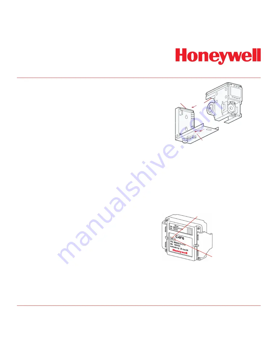
The main chassis can be refitted to the mounting
bracket assembly using the following steps.
1. Align the PCB at the top rear of the main
chassis with the connector located at the
top of the mounting bracket assembly
2. At the same time align the two tubes at
the bottom rear of the main chassis with
the two tubes located on the bottom of the
mounting bracket assembly.
3. Slide the chassis backwards on the
mounting bracket assembly so that the
PCB and connector and tubes engage
simultaneously. (See diagram below).
4. Ensure the PCB, connector and tubes are
fully engaged by firmly pushing the main
chassis horizontally backward on the
mounting bracket assembly
(WARNING: DO NOT PUSH ON THE LCD
AS THIS MAY CAUSE DAMAGE).
5. Align the two attaching screws located at
the bottom of the chassis with the screw
threads on the mounting bracket assembly.
6. Tighten the screws to secure the chassis
to the mounting bracket assembly.
Diagram 4-20. Refitting the chassis.
PCB
CONNECTOR
TUBES
4.9 Installing the Sensor Cartridge
The Midas
®
sensor cartridge is supplied separately
and needs to be fitted to the detector’s main chassis.
The following steps and diagrams detail the procedure
for installing the sensor cartridge for the first time.
This procedure is carried out with the power off and
the detector cover removed.
1. Verify the part number and type of sensor
cartridge is correct for your application, then
remove sensor cartridge from its packaging.
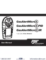
Sensor Cartridge ID Number
Gas ID Number
2. Remove cap from cartridge and bias battery
(if applicable).
3. Add label for secondary gases (if necessary).
4. Align pins at the top of the sensor cartridge
with the socket in the sensor cartridge
chamber.
Summary of Contents for Midas
Page 7: ...Midas Gas Detector 1 1 1 Description ...
Page 9: ...Midas Gas Detector 2 1 2 Overview ...
Page 14: ...Midas Gas Detector 3 1 3 Default Configuration ...
Page 17: ...Midas Gas Detector 4 1 4 Installation ...
Page 41: ...Midas Gas Detector 5 1 5 Startup ...
Page 43: ...Midas Gas Detector 6 1 6 Operation ...
Page 53: ...Midas Gas Detector 7 1 7 Navigating Modes and Submenus ...
Page 74: ...Midas Gas Detector 8 1 8 Maintenance ...
Page 82: ...Midas Gas Detector 9 1 9 Pyrolyzer Module Options ...
Page 89: ...Midas Gas Detector 10 1 10 Optional LonWorks Interface Installation ...
Page 99: ...Midas Gas Detector 11 1 11 Troubleshooting and Fault Diagnosis ...
Page 102: ...Midas Gas Detector 12 1 12 REFLEX ...
Page 104: ...Midas Gas Detector 13 1 13 Internal Web Server ...
Page 106: ...Midas Gas Detector 13 3 Diagram 13 1 IPAddress setting in Windows XP ...
Page 129: ...Midas Gas Detector 14 1 14 Typical Installation Topologies ...
Page 132: ...Midas Gas Detector 15 1 15 Ordering Information ...
Page 136: ...Midas Gas Detector 16 1 16 Specifications ...
Page 139: ...Midas Gas Detector 17 1 17 Calibration and Bump Testing ...
Page 143: ...Midas Gas Detector A 1 A Modbus TCP Interface ...
Page 150: ...Midas Gas Detector B 1 B Gas Tables ...
Page 158: ...Midas Gas Detector C 1 C Warranty ...


