background image

Rev. B 

6-18 

HMXMC001013 


31-Mar-06 

Video Outputs 

The total number of video outputs allowed in a MAXPRO-Net


system is 999. 

Alarm Group 

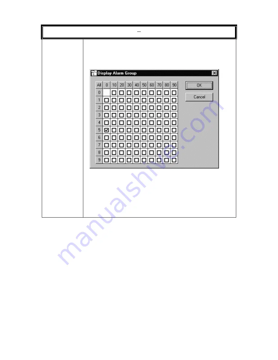
The display of alarms on video output devices may be tailored through 
entries in the Display Alarm Group panel. Each field, if selected, will allow 
the display of alarms from that alarm group on the current video output 
device. 
 

Click on a check box to toggle the alarm display state. Left click on the 
All button to toggle all check boxes.  Click on the numbered button (1, 2, 
3, etc.) to the left of a horizontal row to toggle all the check boxes in a 
horizontal row.  Click on the numbered button (0, 10, 20, etc.) at the top 
of a row of vertical check boxes to toggle all the check boxes in a vertical 
row. 
A check mark in the box indicates the alarm group is selected. 
Click OK to save changes.  Click Cancel to exit the display without 
saving changes. 

Summary of Contents for MAXPRO-Net

Page 1: ...HMXMC001013 March 2006 Rev B MAXPRO Net Crosspoint Matrix Video Switching System Commissioning Manual ...

Page 2: ...Rev B ii HMXMC001013 31 Mar 06 ISSUE DATE REVISIONS A March 2005 Initial Release PCN 1980 B March 2006 Updated installation procedures ...

Page 3: ...of this equipment in a residential area is likely to cause harmful interference in which case the user will be required to correct the interference at his own expense CAUTION Changes or modifications not expressly approved by the party responsible for compliance could void the user s authority to operate the equipment This Class A digital apparatus complies with Canadian ICES 003 Cet appareil numé...

Page 4: ...tion should be moved with care Quick stops excessive force and uneven surfaces may cause the product and cart combination to overturn 10 VENTILATION Slots and openings in the cabinet and the back or bottom are provided for ventilation and to ensure reliable operation of the equipment and to protect it from overheating These openings must not be blocked or covered The openings should never be block...

Page 5: ...e extensive work by a qualified technician to restore the unit to its normal operation e If the unit has been dropped or the enclosure has been damaged f When the unit exhibits a distinct change in performance this indicates a need for service 18 REPLACEMENT PARTS When replacement parts are required be sure the service technician has used replacement parts specified by the manufacturer or have the...

Page 6: ... the literature accompanying the product CAUTION CAUTION TO REDUCE THE RISK OF ELECTRIC SHOCK DO NOT REMOVE COVER OR BACK NO USER SERVICEABLE PARTS INSIDE REFER SERVICING TO QUALIFIED SERVICE PERSONNEL C A U T I O N RISK OF ELECTRIC SHOCK DO NOT OPEN WARNING WARNING TO REDUCE THE RISK OF FIRE OR ELECTRIC SHOCK DO NOT EXPOSE THIS PRODUCT TO RAIN OR MOISTURE WARNING DO NOT INSERT ANY METALLIC OBJECT...

Page 7: ... MERCHANTABILITY FITNESS FOR A PARTICULAR PURPOSE AND NONINFRINGEMENT ARE DISCLAIMED NO ORAL OR WRITTEN INFORMATION OR ADVICE GIVEN BY HONEYWELL ITS EMPLOYEES DISTRIBUTORS DEALERS OR AGENTS SHALL INCREASE THE SCOPE OF THE ABOVE WARRANTIES OR CREATE ANY NEW WARRANTIES SOME JURISDICTIONS DO NOT ALLOW THE EXCLUSION OF IMPLIED WARRANTIES SO THE ABOVE EXCLUSION MAY NOT APPLY TO YOU IN THAT EVENT ANY IM...

Page 8: ...t department Call technical support at 972 620 6500 1 800 796 2288 in North America to register your software via telephone or send an email MAXPRONETREGI HONEYWELL COM to register via email The form can be mailed to the Honeywell s Technical Support Department located at 12880 A Valley Branch Lane Farmers Branch TX 75234 Other information If you wish to minimize the requirement of technical suppo...

Page 9: ... REAL TIME CLOCK RTC 2 1 2 2 VIDEO TEXT INSERTION 2 1 2 3 SMARTEXT 2 2 2 4 HIDING MONITOR TEXT 2 2 2 5 MONITOR BLANKING 2 3 2 6 DYNAMIC TEXT POSITIONING 2 3 2 7 BLACK PAUSE VIDEO SWITCHING 2 3 2 8 SOURCE GROUPING 2 3 2 9 CHANNEL ACCESS BY KEYBOARDS 2 4 2 10 SYSTEM ACCESS BY OPERATORS 2 4 2 11 PRIORITIZING OPERATORS 2 5 2 12 KEYBOARD TIME OUT 2 5 2 13 AUTO SIGN OFF 2 6 2 14 REMOTE CONTROL OF CAMERA...

Page 10: ...NET CROSSPOINT MATRIX VIDEO SWITCHING SYSTEM 3 1 3 2 VIDEO MATRICES 3 1 3 3 CASCADING 3 2 3 4 COMBINING 3 6 3 4 1 Pre selection subracks 3 6 3 4 2 Combiner subracks 3 6 3 5 TEXT INSERTION 3 9 3 6 SUBRACK ADDRESSING 3 12 3 6 SUBRACK ADDRESSING 3 13 3 7 NETWORKING AND TRUNKING 3 16 3 8 CONTROLLING EQUIPMENT 3 18 3 8 1 PTZ Cameras 3 18 3 8 2 Direct Drive PTZ 3 19 3 8 3 Remote PTZ Site 3 19 3 8 4 Vide...

Page 11: ...ILS 6 3 6 5 DEFINING VIDEO INPUT 6 3 6 6 DEFINING VIDEO OUTPUTS 6 12 6 7 DEFINING SEQUENCE TABLES 6 20 6 8 DEFINING CCTV KEYBOARDS 6 22 6 9 DEFINING INTERCEPT KEYBOARD KEYS 6 27 6 10 DEFINING KEYBOARD OPERATOR 6 29 6 11 DEFINING EXTERNAL ALARM INPUT 6 36 6 12 DEFINING AUXILIARY CONTROL OUTPUT 6 40 6 13 DEFINING SYSTEM MACRO LIBRARY 6 43 6 14 DEFINING SPECIAL PARAMETER 6 44 6 15 DEFINING SERIAL POR...

Page 12: ...e 7 11 7 3 2 Locked Scan Sequence 7 11 7 3 3 Guard Tour Sequence 7 12 7 3 4 Network Scan Sequence 7 12 7 3 5 Macro Index Table 7 12 7 4 DEFINE CCTV KEYBOARDS 7 13 7 4 1 CCTV Keyboard 1 7 13 7 4 2 Car Park KB 2 7 13 7 4 3 Control Room 3 7 14 7 4 4 Reception 7 14 7 4 5 Dummy High Level KB 7 14 7 4 6 System Keyboard 7 14 7 4 7 Alarm Keyboard 7 14 7 5 INTERCEPT KEYBOARD KEYS 7 15 7 5 1 Select MON 5 7 ...

Page 13: ...rd Status LED 7 27 7 8 9 High Level Status Output 7 27 7 8 10 Network Auxiliary Output 7 28 7 8 11 VideoBlox Configuration 7 28 7 9 SYSTEM MACRO LIBRARY 7 29 7 9 1 Check All Doors First Second 7 31 7 9 2 Comment Line Only 7 31 7 9 3 Manage Alarm Monitors 7 32 7 9 4 Alarm Zones Active 7 32 7 9 5 Alarm Zones Clear 7 32 7 10 SERIAL COMMUNICATIONS PORTS 7 33 7 10 1 Keyboard Port 7 33 7 10 2 Subrack Po...

Page 14: ...SIONING 8 3 8 2 1 Serial Communication Ports 8 3 8 2 2 Video Inputs 8 5 8 2 3 Video Outputs 8 7 8 2 4 External Alarm Inputs 8 8 8 2 5 Auxiliary Control Outputs 8 9 APPENDIX A MACROS A 1 A 1 MACRO ERROR MESSAGES A 1 A 2 MACRO ERROR REPORT A 2 A 3 KEYBOARD KEYCODES A 4 A 4 STANDARD MACRO COMMANDS A 5 LIST OF TABLES Table 2 1 Settling Conflicts In Monitor Access 2 5 LIST OF FIGURES Figure 3 1 Distrib...

Page 15: ...eo Systems Networked Together 3 17 Figure 6 1 New System Wizard 6 1 Figure 6 2 Import Max Files 6 2 Figure 6 3 Video Input Tab 6 3 Figure 6 4 Video Output Tab 6 12 Figure 6 5 Sequence Table Tab 6 20 Figure 6 6 CCTV Keyboard Tab 6 22 Figure 6 7 Intercept Keyboard Key Tab 6 27 Figure 6 8 Keyboard Operator Tab 6 29 Figure 6 9 External Alarm Input Tab 6 36 Figure 6 10 Auxiliary Control Output Tab 6 40...

Page 16: ...ge Of The Keyboard Operators Tab 7 17 Figure 7 11 Second Page Of The Keyboard Operators Tab 7 18 Figure 7 12 The First Page Of The External Alarm Inputs Tab 7 20 Figure 7 13 The Second Page Of The External Alarm Inputs Tab 7 21 Figure 7 14 The Auxiliary Control Outputs Tab 7 25 Figure 7 15 The System Macro Library Tab 7 29 Figure 7 16 The System Macro Library Tab 7 30 Figure 7 17 The Serial Commun...

Page 17: ...e 8 1 System Block Diagram 8 1 Figure 8 2 Connection Diagram for the VideoBloX system 8 2 Figure 8 3 Serial Ports Tab 8 3 Figure 8 4 Video Inputs tab 8 5 Figure 8 5 Video Outputs tab 8 7 Figure 8 6 External Alarm Inputs tab 8 8 Figure 8 7 Auxiliary Control Outputs tab 8 9 Table A 1 Macro Error Definition Table A 1 Table A 2 Macro Event Codes A 3 ...

Page 18: ...Rev B xviii HMXMC001013 31 Mar 06 Notes ...

Page 19: ...oard Where Video Cassette Recorders are utilized in a MAXPRO Net system the standard control functions stop play record rewind fast forward pause slow mode and optional eject are available from the keyboards Remote control interface of other video processing equipment can also be implemented e g motion detectors freeze frame units video multiplexes quads etc External alarm inputs and auxiliary con...

Page 20: ...environment to work in All possible functions available for use in a matrix video system can be accessed from the keyboards through the keys Cameras monitors VCRs and pan tilts PTZs are just some of the function keys on a keyboard An operator to whom access is permitted can with the correct key press control the allowable system devices Keys can be reprogrammed to incorporate other functions as we...

Page 21: ... subrack This application is very useful for a simple video system having up to 96 video inputs Please refer to section 3 2 Cascading for a more detailed description Combining Two different types of video switching subracks are used Preselection subracks and Combiner subracks The pre selection subracks referred to in Combining are identical to the subracks in Cascading They would be the normal vid...

Page 22: ... control and of course video switching including scanning are all performed simultaneously by the MAXPRO Net Server Application Modules Modules are plugged into the subracks to perform the required tasks in the matrix video system Video switching modules video text insertion modules external alarm input modules and auxiliary control output modules are all available for use in a system The actual n...

Page 23: ...messages are received on the Slave communications port Dependent on the DIP switch settings these commands are then translated to serial data packets which are compatible with other manufacturer s Pan Tilt Zoom telemetry receivers or integrated domes In device control mode generic BossWare device control commands are received and translated into data packets compatible with other manufacturer s VC...

Page 24: ...ule MX205 Enhanced video text insertion module RD315 Two wire PTZ communications controller module RD316 RS 485 PTZ communications controller module RD378E Variable speed 24v AC DC PTZ site receiver RD490 Infra red Peripheral Control Interface module VCR control also supports RS 232 control RD494 Resistive Ladder Peripheral Control Interface module HEGS5000 Standard control keyboard HEGS5300 Enhan...

Page 25: ...ck to execute the designated macro sequence and bring about the desired function 2 2 VIDEO TEXT INSERTION In order for the MAXPRO Net video system to label camera selections display the current time date and provide the user with other system information the text is superimposed onto the displayed video picture This text information is updated by the MAXPRO Net Server whenever necessary to provide...

Page 26: ... purposes During playback the operator can choose whether to reveal or conceal the recorded text information The key on the keyboard is used to toggle between the reveal and conceal display modes Smartext can also be controlled with special commands in the macro programming environment The Smartext data is blended into the video signal in a way that allows recording switching and dubbing using sta...

Page 27: ...ions completed even when pre text insertion is not being used Other monitors can still be defined to a Fixed Text Position even when displaying the same cameras 2 7 BLACK PAUSE VIDEO SWITCHING When a monitor switches from one camera to another frame roll occurs if the camera signals are not synchronized This occurs because the monitor takes time to resynchronize to the new video signal The MAXPRO ...

Page 28: ...llocated keyboards are allowed to access and select video sources cameras etc on that video output channel Where the video output channel is a monitor only the allocated keyboards will be able to select that monitor for use This means that monitors that are located somewhere other than at the control room where the keyboard is being used cannot be selected or controlled Note To use a keyboard it m...

Page 29: ...nflict Operational Outcome HIGHER versus LOWER The Higher priority operator displaces the Lower priority operator from the monitor SAME priority levels Both operators have equal and concurrent access to the monitor EXCLUSIVE versus ANY OTHER The Exclusive priority operator always displaces any other priority from the monitor except for another exclusive priority EXCLUSIVE versus EXCLUSIVE The firs...

Page 30: ...ble 1 Direct relay control using an output module in one of the I O subracks giving control of pan tilt and lens functions 2 Two wire data communications to a variable speed pan tilt site receiver for controlling AC and DC pan tilt units and lens control at variable speeds 3 Fixed speed 4 Variable speed 5 High speed PTZs Domes 6 RS 485 of third party PTZ Dome equipment 2 14 2 VCR Control The MAXPR...

Page 31: ...etection modules are installed The camera fail detection module RD 89 would have to be installed into every primary video switching subrack used in the video system Three types of video fail are checked for every camera being monitored even while the cameras are not displayed on a monitor 2 15 1 Lost video If a camera fails or its video cable is broken i e a complete loss of video sync then a LOST...

Page 32: ...run on two or more monitors at the same time the same camera selections are displayed at the same time on the monitors synchronized Note Camera selections or entries in scan sequences can within the limitations of source grouping for that monitor be displayed in any order as desired 2 16 1 Guard tours Scan sequences that do not wrap back around are called guard tours When a guard tour is executed ...

Page 33: ...he usual commissioning environment The cold boot macro sequence is specified in the configuration editor the SETMAX program is discussed in Chapter 6 It can also access macro sequences from the system macro library User can cold boot the server from SetMax 2 20 WARM BOOT MACRO If a subrack reset occurs while the system is running then the system is re initialized and the warm boot macro is execute...

Page 34: ...er this alarm The proper system response to such an alarm condition should be programmed in the camera s START MACRO sequence 2 21 2 PTZ site fail alarms In some video systems the PTZ site receivers used for particular cameras are continuously monitored If a site should fail to communicate with the video system i e blown fuse cut cable etc an alarm will occur To ensure proper system response for s...

Page 35: ...isplay their text messages on one monitor or several monitors simultaneously Note Alarm display group 0 can NEVER be displayed So any alarm assigned to alarm display group 0 will never display a text message on any video output channel The alarm will still execute its macro sequence 2 23 THE ALARM STACK Whenever an alarm becomes active it is placed onto the alarm stack If several alarms become act...

Page 36: ... are general purpose output circuits relay contact or opto output which can be used to control devices and equipment external to the normal video system s equipment Unlike camera PTZ control or VCR remote control etc auxiliary control outputs are not related to any video input source or dependent on any particular video selection prior to activation They are controlled by pre programmed macro sequ...

Page 37: ...eople believe that any full matrix video switcher will allow any video input to be selected to any video output at any time however this is generally incorrect Many full matrix systems suffer from trunking limitations which restrict the number of video outputs that may be selected concurrently from any group of video inputs These input groups are a function of the hardware design of the switcher a...

Page 38: ...e distributed across the entire subrack Each video switching module occupies a single video output channel or slot Each slot can access any of the 32 video inputs contained within the switching module Each slot also has a cascade input Video coming into the cascade input is only available to the video switching module in that video output channel It is not distributed across the subrack and cannot...

Page 39: ...hing Subracks The video outputs from the first subrack get fed into the corresponding cascade inputs of the second subrack Each slot in the first subrack is able to select any of its own 32 video inputs However in addition to its 32 video inputs each slot has a cascade input to select video from ...

Page 40: ... This method of increasing video inputs should only go through a maximum of three video switching subracks in one cascade configuration This ensures that high a quality video signal is maintained Example Of Selecting Video Input 45 Using the cascading configuration figure 3 2 above the following diagram shows what happens when video input 45 is selected onto monitor 2 For illustration purposes mon...

Page 41: ...ack can select this video input which is not physically connected to it through its cascade input as illustrated in figure 3 4 Video input 3 is physically connected to the first subrack The video switching module in channel 2 of the first subrack connects video input 3 to its video output The video output is connected to the cascade input of the corresponding video switching module in the second s...

Page 42: ...subrack Combiner subrack 3 4 1 Pre selection subracks The pre selection subracks used in combining are normal video switching subracks They are identical to the ones used in the previous cascading example with video inputs distributed across the entire subrack 3 4 2 Combiner subracks Combiner subracks are different from the pre selection subracks because video inputs to the combiner subrack are no...

Page 43: ...ach channel only accepts a single video input from each pre selection subrack i e Output 1A from the first pre selection subrack A connects to the first input A of channel 1 of the combiner subrack The second output from the first pre selection subrack A 2A connects to the first input A of channel 2 of the combiner subrack This goes on until the Nth output from the first pre selection subrack A is...

Page 44: ...subracks A B and C Figure 3 6 Selecting Video Input 3 To Channel 1 Video input 3 is located on pre selection subrack A Therefore the video switching module in channel 1 of pre selection subrack A gets instructed by the System Controller to select the desired video input and put it on its output 1A When selecting video inputs 1 32 all channels in the combiner subrack would select the A input If vid...

Page 45: ...switching modules However for the ease of system design and maintenance special subracks are available to house text inserter modules In a normal video system each video output channel has a text inserter assigned to it In the system s configuration editor the SETMAX program each text inserter is individually addressed Therefore a video output channel from subrack 10 can have its text inserter in ...

Page 46: ...Rev B 3 10 HMXMC001013 31 Mar 06 3 5 TEXT INSERTION CONTINUED Figure 3 7 Cascading Configuration With Post text Insertion ...

Page 47: ...d therefore the video output from the text inserter module has text superimposed onto it before being displayed Figure 3 8 Combining With Text Insertion In combining figure 3 8 the text inserter modules are placed between the combiner subrack and the monitor for each video channel and therefore the video output from the text inserter module has text superimposed on it before being displayed on a m...

Page 48: ...T CHANNELS GROUP 1 1 32 GROUP 2 33 64 GROUP 3 65 96 GROUP 4 97 128 GROUP 5 129 160 GROUP 6 161 192 GROUP 7 193 224 GROUP 8 225 256 SUBRACK ID NUMBER 001 099 101 199 201 299 301 399 401 499 501 599 601 699 701 799 Figure 3 9 Grouping Of Subracks The first digit determines the group of video output channels 1 8 that the subrack supports A System With 30 Video Output Channels A video system having 30...

Page 49: ...001013 31 Mar 06 3 6 SUBRACK ADDRESSING CONTINUED Figure 3 10 Subrack IDs For 30 Output Channels Although the subrack IDs can be any number between 001 099 you should always choose a systematic method of numbering them ...

Page 50: ... the second group of subracks that support the last 8 video output channels 33 40 would range from 101 199 Figure 3 11 Subrack IDs For 40 Output Channels With the same cascading configuration the number of output channels can be easily expanded In the preceding example a total of six subracks are now used to preserve a full matrix structure The second group of three subracks is the same as the fir...

Page 51: ... from 201 299 Figure 3 12 Subrack IDs For 80 Output Channels A systematic method of numbering the subracks in all three groups has been maintained Note Although it is not advisable subrack IDs need not run sequentially within its group but they must be independent The three examples sited in this section figure 3 10 figure 3 12 are by no means the only configurations suitable in designing a system...

Page 52: ... two network nodes using the Ethernet Tab of SetMax Configurator Video trunk lines are used to automatically route camera and VCR video signals between the network system nodes MAXPRO Net Supports Networking over LAN Trunk Lines Video trunk lines are a single video circuit linked from the output channel in one system node to a video input on the matrix of the other system node It is used to dynami...

Page 53: ...de 3 can also be operated from both the main system node 1 and satellite system node 2 The door status would also be available for conditional testing in the macro programming environments of all three video system nodes Other internal system status is also provided to all system nodes These include camera fail alarms PTZ site fail and tamper alarms VCR alarms time and date synchronization and sys...

Page 54: ...ould be added to a system to decrease the occurrence of congestion 3 8 CONTROLLING EQUIPMENT The MAXPRO Net video system supports a fully integrated environment where all cameras VCRs and other video equipment can be controlled from a keyboard When control keys or joystick are activated on the keyboard the video system must first determine What is the currently selected monitor What camera or VCR ...

Page 55: ...commissioned in a variety of ways Fixed Connects in series between the video output channel after the text inserter and the video monitor It can record whatever is displayed on that monitor and can only playback onto that monitor Dynamic A video output channel is connected to the video in and the video out is connected back to the video input matrix The VCR can record any camera that can be displa...

Page 56: ...m status is automatically managed and associated to the VCR by the MAXPRO Net system 3 8 4 4 Resistive Array VCR interface One peripheral control interface PCI module would be used to control up to eight 8 VCR machines using the two wire resistive array remote control feature available on some 24 hr time lapse and real time industrial video recorders Again up to 16 control functions could be suppo...

Page 57: ...e Operator to do the Configuration changes in SetMax and upload the new configuration details to MAXPRO Net Server with out restarting the MAXPRO Net Server 3 8 8 MaxMon Utility MaxMon utility allows users from different locations to connect to the MAXPRO Net server and perform remote diagnostic operations MaxMon supports the following functionalities Online transaction This is the MAXPRO Net inte...

Page 58: ...ontrol the Output devices Camera test mode MaxMon provides Camera test mode that allows the user to directly interact with the camera This mode will be helpful in configuring specific features in the camera E g like Preshots 3 8 9 VideoBlox integration MAXPRO Net can control VideoBlox Devices Please refer to the SetMax manual for configuring VideoBlox devices 3 8 10 Setmax and MaxMon connection ov...

Page 59: ...MAX1000 system These hardware panels are no longer available with the MAXPRO Net hardware However the MAXPRO Net configurator supports configuring these panels in systems where the software is being upgraded Refer to the MAXPRO Net Software Configuration User Guide for configuring mimic panels in existing system installations ...

Page 60: ...Rev B 4 2 HMXMC001013 31 Mar 06 Notes ...

Page 61: ...dit the MAXPRO Net system configuration Please refer to the MAXPRO Net Software Configuration User Guide for detailed information 5 3 MAXPRO Net Licensing On New Installation On the first installation the product is licensed for a trial period of thirty days During this period the message LIC XX_DAYS_LEFT is displayed during start up on all monitors This message is also written to ErrorLog Any Max...

Page 62: ...s can be performed The message LIC EXPIRED will be displayed on all the monitors for every switch operation MaxMon will display a message box indicating that the license is expired and all the menus will be disabled Updating License Please refer to the SetMax Manual Section 2 4 for more information ...

Page 63: ...ays 1 New System Wizard 2 Importing Existing Max Files and rebooting the system 6 2 INITIALIZING THROUGH THE NEW SYSTEM WIZARD Open SetMax from the Program Menu or by double clicking the Shortcut Icon of SetMax from the desktop Then Select Tools New System Wizard from the menu bar to open the New System Wizard Dialog Figure 6 1 New System Wizard ...

Page 64: ...n make changes in the configuration details Click the Save All button and reboot the server by clicking the Cold Boot button on Setmax Now the newly configured details get loaded to the MAXPRO Net Server Note For more details refer to the MAXPRO Net Software Configuration User Guide 6 3 INITIALIZING BY IMPORTING EXISTING MAX FILES Select Tools Import Max Files Figure 6 2 Import Max Files The Brows...

Page 65: ...xplain each tab present in SetMax and also explain each field displayed in each tab 6 5 DEFINING VIDEO INPUT Selection of the Video Inputs tab opens the file for editing the properties for each video input The details for each field in the file are described below Figure 6 3 Video Input Tab ...

Page 66: ...lect the device type from the list box as shown below or type in the required device most of the device types are selectable by merely typing in the first character e g c or C will automatically select Camera The currently supported video input device types are as follows Camera fixed and PTZ VCR video cassette recorder dedicated or Dub VCR Smart Device devices such as multiplexers Standard Device...

Page 67: ...ext insertion whenever the video input device is selected It is also used by video fail alarms to identify the failed video input device Enter the desired description up to 18 characters in the field and press Enter on the keyboard Primary Subrack ID This is the address of the subrack to which the video input is physically connected Valid primary subrack addresses range from 1 99 A value of 0 indi...

Page 68: ...igurations In a cascading configuration consisting of three subracks the COMBINER SUBRACK ID contains the address of the second subrack that is to be bypassed when selecting the current video input device For more details please refer to the CASCADING section of the Commissioning Manual The following figure shows typical entries for a cascaded system In combining configurations this field contains...

Page 69: ...value and indicates no alternate camera is defined Alternate Camera View The alternate camera can also be a PTZ camera with view recall capability In this case an actual VIEW number can be specified pressing the ALT key will now not only display the alternate camera but will also automatically move it to the designated VIEW preset position The valid camera views range is 1 99 0 is the default valu...

Page 70: ... the CONTROL OFFSET field can be used to define the output number on the controller card in the specified subrack slot The valid range of output numbers is 1 8 A 0 indicates that a hardwired relay output module is being used in the subrack slot for controlling the device For VideoBlox Subrack this represents the camera number of the video input channel Valid range 1 to 255 Source Control Cont Avai...

Page 71: ...CR etc can be locked to prevent user control of the device The default lock unlock status is specified here Note This locked status can be unlocked by the system operator if they have the necessary System Access Level from the MAXPRO Net Menu System using MaxMon Source Disable When a video input needs to be temporarily removed from the video input selection table the SOURCE DISABLE field would be ...

Page 72: ...ress is 1 For pretext slot numbers 17 to 32 MVT address is 2 X Y These two fields define the horizontal X and vertical Y location of the pretext The valid positions are 1 13 These X and Y coordinates are also the dynamic text coordinates where this feature is enabled for video output channels Dynamic Equalization Where text insertion modules that support dynamic cable equalization are utilized thi...

Page 73: ... 11 33 64 12 65 96 13 97 128 14 Enter a 0 when video fail detection is not required NOTE This is valid for cameras and trunk inputs only For video inputs of other device types this field will NOT accept an entry For VideoBlox Subrack the Video fail slot should be 1 Start Macro The START MACRO is executed whenever a video alarm condition is detected for the corresponding video input device The vide...

Page 74: ...1 Mar 06 6 6 DEFINING VIDEO OUTPUTS Selection of the Video Outputs tab opens the file for editing the properties for each video output The details for each field in the worksheet are described below Figure 6 4 Video Output Tab ...

Page 75: ...1 32 corresponding to physical outputs 1 32 Note BE CAREFUL when redefining slot numbers Source grouping must be used to prevent camera selections across matrix hardware boundaries To change the slot number type the desired number and press Enter on the keyboard Device Type Each video output device has a device type to indicate to MAXPRO Net what selection and control parameters apply to the devic...

Page 76: ...desired description up to 18 characters and press Enter on the Keyboard Text Inserter Subrack This field defines the address of the subrack which contains the text insertion card MX208 RD200 RD205 MX205 RD220 for this video output device The valid range of subrack addresses is 1 799 a value of 0 indicates text is not used Enter the desired value and press Enter on the keyboard For VideoBlox Subrac...

Page 77: ... when enabled will make the entire text window background BLACK R the reverse black white flag when enabled will reverse the allocation of BLACK and WHITE D the double height flag when enabled will DOUBLE the text height F the flash flag when enabled will allow the text to flash continuously on screen E the Enhanced text flag when enabled will allow an Enhanced Text Card RD 205 to be used on this ...

Page 78: ...l picture on display The display time out period can be set from 1 999 seconds Enter a zero 0 in this field if the display time out function is not required Net Device When the current video output device is actually connected to another MAXPRO Net system within a network configuration the NET DEVICE field is used to specify the exact location and reference for the video output device e g 03 M12 t...

Page 79: ...rom the system menu using MaxMon while MAXPRO Net is running and via macro control Source Group Each video output device may be granted access to any of the source groups which are allocated to every video input device This allows the system to control which video output channels have access to which video inputs Due to hardware restrictions some monitors may only be able to access certain video i...

Page 80: ...rent video output device Click on a check box to toggle the alarm display state Left click on the All button to toggle all check boxes Click on the numbered button 1 2 3 etc to the left of a horizontal row to toggle all the check boxes in a horizontal row Click on the numbered button 0 10 20 etc at the top of a row of vertical check boxes to toggle all the check boxes in a vertical row A check mar...

Page 81: ...tal row Left click on the numbered button 0 10 20 etc at the top of a row of vertical check boxes to toggle all the check boxes in a vertical row A check mark in the box indicates the keyboard has access to the video output device Click OK to save changes Click Cancel to exit the display without saving changes Macro Flags This field allows for definition of the default cold boot state of the macro...

Page 82: ...ls for each field in the file are described below Figure 6 5 Sequence Table Tab Sequence Tables SEQ This field serves as a reference number identifier for the sequence table it is not a changeable field Type There are three kinds of sequence types available Scan During a SCAN sequence operation camera selection entries are wrapped around when the end of the scan sequence is reached This mode of op...

Page 83: ...the sequence type is Scan or Tour this field defines the dwell time in seconds each camera will be displayed before automatically advancing to the next camera Valid dwell periods are 1 99 seconds If the sequence type is defined as Index then this field becomes table position 0 The range of entry values is 0 9999 01 to 99 When the sequence type is Scan or Tour these fields define which cameras will...

Page 84: ...is NOT a changeable field Note Keyboard ID 100 represents the system keyboard By default this keyboard can access and control all monitors It can be signed off if not required Description This is an 18 character description used to identify the keyboard It is displayed on the currently selected video output device if the current operator is not selected for display i e the operator has not logged ...

Page 85: ...t system is first powered up This means the keyboard can immediately select a video input device for display without first having to select a monitor Valid default monitor values are 1 999 A value of 0 means no default monitor selection has been made Enter a value in the field and press Enter on the keyboard Default Operator This field specifies which operator number is automatically logged onto t...

Page 86: ... text to the keyboard LCD Monitor Camera the video output device description text and the video input channel device description are displayed on the LCD Camera Time Date the video input device description and the current time and date are displayed on the LCD Current Alarm the active alarm description as displayed on the currently selected video output device is displayed on the LCD Message Mode ...

Page 87: ...nse to warning messages eg trying to pan tilt a fixed camera Alarm Prompt The keyboard will beep continuously in response to an alarm message until the alarm is cleared Deadman Tone keyboard will beep if keyboard is not used for specific amount of time as defined by keyboard operator section To deselect all audible keyboard prompts click on the Deselect All button then click on OK When done select...

Page 88: ...a VCR Control the post event macro is executed every time the keyboard is used for control of a VCR All keys the post event macro is executed for every key press on the keyboard To select or deselect all events click on the Select All or Deselect All button When done selecting events click on the OK button To exit the field without changing the current selections click on the Cancel button Device ...

Page 89: ...his field enter the key code of the key that is to be intercepted For a complete list of keyboard key codes please refer to Appendix A located in the Commissioning Manual If the key code entered in this field has a default description it is automatically displayed in the description field Enter the desired key code then press Enter on the keyboard Description If the key code field has been left bl...

Page 90: ...K button To exit the keyboard dialog box with making any changes click on the Cancel button Key Replacement Macro When the specified key press on the selected keyboards is detected the KEY REPLACEMENT MACRO is executed This can be used to perform automatic system control functions Please refer to the MACRO GUIDE in the Operator s Manual for more details on the macro functionality Enter the desired...

Page 91: ... This is an 18 character description used to identify the current operator It is displayed on a monitor or other video output channel with text insertion whenever that operator uses a keyboard Enter up to an 18 character description and press Enter on the keyboard Note The Display Name in the OPERATOR PRIVILEGES field must be enabled for the name to be displayed Otherwise the description of the ke...

Page 92: ...r priority operator from the monitor Same priority levels Both operators have equal and concurrent access to the monitor Exclusive versus any other The exclusive priority operator always displaces any other priority from the monitor except for another exclusive priority Exclusive versus exclusive The first exclusive priority operator will prevent the other from accessing the monitor on a first in ...

Page 93: ...ard Source Group Access Each operator may be granted access to any of the video input source groups This field is used to restrict operators from viewing video input devices in selected source groups Click on the check box to select or deselect an operator source group access To select all or deselect all source groups click on the All button If the box contains a check mark it indicates the opera...

Page 94: ...d alarm group To select or deselect all Alarm Groups click on the All button Click on any of the check boxes to toggle the selected alarm group access For example to give an operator access to alarm group 79 click on the check box in column 70 row 9 until there is a check mark in the box When done selecting or deselecting click on the OK button To exit the dialog box without making any changes cli...

Page 95: ...era when it is being used by this operator Multiple Sign On When enabled allows the current operator to be signed on to more than one keyboard at a time Access Privileges Scan Set When enabled allows the operator to edit scan sequences User Macro Set Allows the operator to create user keyboard macros Camera View Set Allows the operator to set PTZ camera views Control Privileges This section allows...

Page 96: ...put Disable when enabled allows the operator to enable or disable video input devices A disabled video input device cannot be displayed on any video output device by any operator Vinput Control Lock Unlock when enabled allows the operator to lock or unlock controls of video input devices A locked video input device cannot be controlled by any operator Scan Sequence Lock Unlock when enabled allows ...

Page 97: ...nabled allows the operator to change the current video system status System Configuration when enabled allows the operator to run the Windows SetMax configuration editor save the current system environment as the default settings or exit to Windows When all operator privileges are set click on the OK button To exit the Operator Privileges dialog box without making any changes click on the Cancel b...

Page 98: ...utput devices When an alarm is detected the alarm group number is used to determine which video output device will display the associated alarm message text Valid values are 0 99 Enter the desired alarm group number and press Enter on the keyboard Note Alarm groups 1 99 can display alarm message text onto video output channels Alarm group 0 is always a non displayable alarm group Alarms in this gr...

Page 99: ...pecified Entering data in this field will clear the Subrack ID and Subrack Slot fields Valid camera numbers are 1 9999 This field should be set to zero 0 when an alarm input module in a subrack is used Enter a camera number or zero 0 and press Enter on the keyboard There are 8 separate alarm inputs for every subrack slot defined as an alarm input slot The actual alarm input used must be specified ...

Page 100: ...ed You may either select the required operating mode from the list box as shown below or by typing in the first letter of the required option When the desired mode is highlighted in the list box or in the field press Enter on the keyboard Alarm Disable When the MAXPRO Net system starts running each alarm can be either enabled or disabled by default Yes disables the alarm No enables the alarm You m...

Page 101: ... the NETWORKING section of the user s guide Enter the location and reference for the alarm input if applicable and press Enter on the keyboard Alarm Start Macro When an alarm condition is detected for an alarm input the ALARM START MACRO is executed This can be used to perform automatic system control functions Please refer to the MACRO GUIDE for more details on the macro functionality Enter the d...

Page 102: ...n This is an 18 character description used to identify the control output It is not used by MAXPRO Net at all and it is purely for operator reference Enter up to an 18 character description and press Enter on the keyboard Subrack ID Specifies the subrack ID number where the control output module resides The valid range is 1 99 If a high level or mimic panel output is being used the number is prefi...

Page 103: ... Bit Selecting this field brings up a dialog box which allows configuration of the separate output circuit called output bits being used Click on the check box to the left of an output bit to toggle its state If the box to the left of the output bit contains a check mark the bit is controlled by the Auxiliary Control Output Each control output defined in SetMax can control 1 or more output bits Cl...

Page 104: ... MAXPRO Net system starts running each control output can be set to On or Off by default You may either select the required output default state from the list box as shown below or by typing in the required option When the desired state is displayed in the field press Enter on the keyboard ...

Page 105: ...ese other sources Figure 6 11 System Macro Library Tab System Macro Library Ref The system macro library reference number is purely a reference number used to distinguish one system macro from another The MAXPRO Net system will CALL a system macro by its reference number The System macro library reference number field is NOT a changeable field Description The description text is used to label the ...

Page 106: ...n of the Special Parameters tab allows for direct editing of all the special system parameters These fields default to values that are satisfactory for most video system applications The details of each of the properties are described below Figure 6 12 Special Parameter Tab ...

Page 107: ...pretext subracks Pretext Double Double height text inserted by pretext subracks Information Lines The columns on the table represent the types of information that are displayed as text Not all information line types are available for every text type and height Real Time Clock Line Defines the line the Real Time Clock is displayed Video Source Description Defines the line the Video Input device des...

Page 108: ... Click on the Select All button to select all the features Note The Select All button selects the Hidden Text Card with Double Height and Shadow features selected If all features are selected Click on the Deselect All button to deselect all features When the Pretext Display Status is set as desired Click on the OK button If you want to exit the dialog box without making changes click on Cancel Ena...

Page 109: ...ported to the printer For a print out of all groups type ALL in this field Note If automatic event printing is not required but access to the printer is still needed from within the macro environment enter an unused alarm group number in the alarm group field Errorlog Printing If this field contains a checkmark error log messages are sent to the printer The type of error log messages sent to the p...

Page 110: ...ter the network node number or zero in the field and press Enter on the keyboard Note The Network node ID will not be live updated to the server Master Network Clock Click this field to select this node in a networked system to be the master clock If this field is selected once each hour all other network nodes will have the time and date synchronized to this node s clock Note Only one network nod...

Page 111: ... when the desired equipment settings are selected To exit the Equipment Setting dialog box without making changes click on the Cancel button Cold Boot Macro When the MAXPRO Net Server is powered up or reset the COLD BOOT macro sequence will be executed following all normal system and equipment initialization Please refer to the MACRO GUIDE in the Operator s Manual for more details on the macro fun...

Page 112: ...unk can be stolen if an alarm condition causes a system macro to make a video selection An operator cannot steal from another regardless of priority Never Steal Trunks are assigned on a first come first serve basis regardless of operator priorities click on the desired selection Forward Net Broadcast In network environments it may be required to suppress the forwarding of incoming broadcast messag...

Page 113: ...ideo Select displays every video switching action in the system Control displays every control action for PTZ cameras VCRs etc Auto Number No data is displayed on the menu output in this test mode However if this mode is selected description text displayed on video output devices will show the logical device number of the device at the start of the text line Click on the desired selection in the p...

Page 114: ... history by connecting MaxMon to the server Note Enabling this option will slow down the server This is used mainly for debugging purpose Ethernet Port Number This field defines the port number used by the clients SetMax or MaxMon to connect to the server over the Ethernet The default port number will be 26026 Note The Ethernet Port No will not be live updated to the server 6 15 DEFINING SERIAL PO...

Page 115: ...n is selected Only one port can be selected as a printer port Auxiliary if a port is selected as auxiliary it can receive any valid MAXPRO Net protocol command message Data can be sent from the port using a direct port write from a system macro Please refer to the MACRO GUIDE for more details of macro functionality Error Log All data saved to the errorlog file is also sent out of the serial port O...

Page 116: ...99 Enter the desired value in each ID field and press Enter on the keyboard Note This is not applicable for VideoBlox For VideoBlox Subrack ID3 ID4 these two fields represent the video loss source device type 0 0 represents video loss source device is Input cards 0 1 represents video loss source device is Concentrator 1 0 represents video loss source device is MVT or pretext devices 1 1 represents...

Page 117: ...ll down menu Click on the desired setting Data Bits The number of data bits per character can be selected as either 7 or 8 The default value is 7 To change the data bits setting click on the down arrow to open the pull down menu Click on the desired setting The value can also be typed into the field Stop Bits The number of stop bits per character can be selected as either 1 or 2 The default value ...

Page 118: ...trol output range error 09 Invalid numeric evaluation error 10 Macro timer range error 11 Macro timer command error 12 Macro timer period error 13 System macro range error 14 Unknown video output channel 15 Unknown video input source 16 Invalid external alarm control logic 17 Invalid auxiliary output control logic 18 Invalid camera disable logic 19 Invalid PTZ speed 20 Unknown system constant erro...

Page 119: ...e error in Blank Channel command valid 0 3 only 52 Unknown Special WORD command E g WARM BOOT etc 53 Other errors detected during Cold Warm Boot Check ERRORLOG As well as the macro error number details of the macro trail are also given in the Error Log The macro trail details the actual event that caused the macro to begin execution which is given as a 2 letter code and lists the system macro line...

Page 120: ...n Print Errorlog from the menu bar in SetMax configurator To clear the Error Log database select Edit then Delete or select the delete button from the toolbar when the Error Log is being displayed 6 17 TITLE REGISTERING The Title and Registration window provides details of the license information for the MAXPRO Net software Some of the fields are fixed and some can be edited depending on the acces...

Page 121: ...otected from unauthorized editing The next time SetMax is run the user will be prompted with a logon message If the user enters the correct Distributor Password all the files can be edited The Distributor Password can contain up to 8 characters If this field is left blank and the Client Password is also left blank SetMax can be run without entering a password Client Password The Client Password ha...

Page 122: ... inputs The details of each of the Logical Camera Selection properties are described below Figure 6 15 Logical Camera Selection Tab Logical Camera Selection REF The logical group reference number is purely a reference number used to distinguish one logical group from another The logical group reference number field is NOT a changeable field Logical Group Description This is an 18 character descrip...

Page 123: ...rds may be given access by selecting its corresponding field Click on any field to toggle the keyboard access state If a field contains a check mark that keyboard has access to the logical camera group To select or deselect all keyboards click on the All button When the keyboard access is configured press the OK button To exit the Keyboard dialog box with making changes press the Cancel button ...

Page 124: ... to 99 different selection numbers per group Valid values are 1 9999 Primary Camera This field holds the Camera Number that is selected when the operator has selected a Group and a selection number within that group Valid values are 1 9999 and must correspond to a camera number defined in the Video Inputs table Primary View The primary camera can also be a PTZ camera with view recall capability In...

Page 125: ... which indicates no camera view is to be selected Note As the view number 0 is used to indicate that NO VIEW is specified view 0 can NOT be recalled by this field Alternate Camera 2 This field defines the second alternate camera to be selected when the ALT key is pressed again after selecting alternate camera 1 The range of valid camera numbers is 1 9999 The alternate camera 2 would have to be def...

Page 126: ...EMENT Selection of the VCR Management tab allows for direct editing of the properties associated with VCR Management The table is divided into 3 groups The details of these groups and the properties of each are described below Figure 6 16 VCR Management Tab ...

Page 127: ...ich Dedicated VCRs reside in each bank valid VCR numbers are 1 9999 N B the VCR number the camera number being recorded by the dedicated VCR Manual Start Input Where Tape change sequencing is to be initiated manually this field is used to define the external alarm input which will be used to begin Tape change operations on this bank Upon entry of a value into this field SetMax will automatically a...

Page 128: ...elongs valid entries are 1 9 Default Camera When the standby VCR is not in use providing backup recording it is useful to have it recording something of value This field allows definition of a default camera which will be recorded by the standby when it is not otherwise in use Valid entries are 1 9999 Use For Tape change Each standby VCR is configurable as to what functions it will be used for All...

Page 129: ...1 9 Manual Start Input Where Tape change sequencing is to be initiated manually this field is used to define the external alarm input which will be used to begin Tape change operations on this bank Upon entry of a value into this field SetMax automatically adds the appropriate definitions to the External Alarm Inputs table The range of valid entries is 1 9999 the default value is 0 indicating Tape...

Page 130: ...CR numbers are 1 9999 N B the VCR number the monitor number being recorded by the logging VCR Manual Start Input Where Tape change sequencing is to be initiated manually this field is used to define the external alarm input which will be used to begin Tape change operations on this bank Upon entry of a value into this field SetMax will automatically add the appropriate definitions to the External ...

Page 131: ...vidual tape change schedules may be defined GENERAL SETTINGS Time This field specifies the start time for tape change operations valid entries are 00 00 23 59 VCR Bank Selecting a VCR Bank field enables display of a list of the currently defined banks The order in which these banks are displayed within the schedule is the order in which tape change operations will occur ...

Page 132: ...s of the late rewind operation If this check box is disabled VCRs that were bypassed during tape change operations will return to the record mode when the review operation terminates GENERAL SETTINGS CONT VCR Alarm Group VCR management provides enhanced alarm handling capabilities for dedicated standby and logging VCRs An alarm will only be generated when a VCR ceases to record for reasons outside...

Page 133: ...ed VCR Review Key For each keyboard the key used to initiate review of dedicated VCRs is definable Placing an entry in this field will automatically add entries to the Intercept Keyboard Keys table Logging VCR Review Key For each keyboard the key used to initiate review of logging VCRs is definable Placing an entry in this field will automatically add entries to the Intercept Keyboard Keys table S...

Page 134: ...ro Back Control The Zero Back functionality provides a convenient means of locating the position on tape where recording was terminated due to a review taking place When zero back control is enabled the tape counter is zeroed at the moment of review initiation When the review is complete but prior to selecting the Review End key the operator presses the Zero Back key to initiate an automatic searc...

Page 135: ...ration this field defines the time period in seconds required to fully rewind the tapes Valid values are 10 999 seconds Rewind Settings Inter bank Delay During automatic Tape change operations this field specifies the time period in seconds which should elapse from the sensing of record status on the current bank of VCRs to the beginning of Tape change operations on the next bank Valid values are ...

Page 136: ...umber used to distinguish one port from another There can be up to 100 ports defined in a single video system The reference number field is NOT a changeable field Device Type Only Network device type is configurable Description This is an 18 character description used to identify the selected Ethernet communication port It is used for reference only Enter up to 18 characters in this field and pres...

Page 137: ...ort number on which two MAXPRO Net servers communicate Note Port Number should be 26026 by default This is the Ethernet port number configured in the Special Param of the networked MAXPRO Net Device ID Device ID is a Node ID of the networked MAXPRO Net Server Configured in IP Address column ...

Page 138: ...Rev B 6 76 HMXMC001013 31 Mar 06 Notes ...

Page 139: ...xamples of how video input sources can be defined Several types of camera and VCR definitions are given The description text field would normally be used to display the identity of the video input selection Here it indicates the type of example given Figure 7 1 First Page of The Video Inputs Tab ...

Page 140: ...Rev B 7 2 HMXMC001013 31 Mar 06 7 1 VIDEO INPUTS CONTINUED Figure 7 2 Second Page of The Video Inputs Tab ...

Page 141: ...Rev B 7 3 HMXMC001013 31 Mar 06 7 1 VIDEO INPUTS CONTINUED Figure 7 3 Third Page Of The Video Input s Tab ...

Page 142: ... defined as a PTZ camera Pan tilt zoom focus preset views and flashback controls are supported by this camera This camera s Site receiver is identity 10 and connects to an RD 315 module located in slot 16 of subrack 40 NOTE Note that the WASH WIPE and IRIS functions are not enabled for this PTZ camera example Whatever warning needed 7 1 3 Pseudo Camera Camera 3 is defined as a pseudo camera This m...

Page 143: ...amera has been LINKed into the network in the NET SOURCE field This means that it is also available to another video system node for selection Camera failed status would also be broadcast into the network so other video system nodes can also display the detected camera fail alarm condition 7 1 5 Camera with Pre text Usually camera identification text is inserted in to the video picture at the outp...

Page 144: ...It is not dedicated to any specific monitor The returned video signal out from the video recorder is connected to a video input on the matrix Associated with this video input definition is the control declaration for this VCR In this example control is defined as device 8 of the PCI module RD 490 located in slot 17 of subrack 40 This would probably be using the infra red interface of the VCR NOTE ...

Page 145: ...w video output channels can be defined Several types of monitor and VCR definitions are given Again the description text field would normally be used to display the identity of the video output channel Here it is indicating the type of example given Figure 7 5 First Page of Video Outputs Tab ...

Page 146: ...elect cameras that have been assigned to source group 0 or 3 This monitor can be controlled from any keyboard 1 to 32 This monitor is allocated post text insertion for identification and time date display The associated text module is located in slot 2 of subrack 1 WARNING It is assumed that this is a single video subrack system Slot 2 in the video output table has not been defined to avoid confli...

Page 147: ... 7 2 4 Auto blank Monitor MON 4 is defined as an auto blanking monitor When left unchanged for 10 seconds this monitor will automatically select a BLANK video input This usually would be a black video source so that the monitor s display would remain dark The text insertion for this monitor would also be hidden Auto blanking monitors are generally used to remove non essential pictures from a contr...

Page 148: ... to any one monitor for display or record Together with it s definition in the video input table VCR 1 is a stand alone device that can be utilized by one or more operators Cameras can be selected to it for recording while the output signal from the VCR can be displayed on any monitor While that monitor is displaying VCR 1 pressing the control keys on the keyboard stop play record etc will automat...

Page 149: ...access to source group 0 It is defined to automatically select cameras 003 002 and 001 with a dwell period of 5 seconds between selections This scan sequence can also be changed by an operator during use 7 3 2 Locked Scan Sequence SEQ 2 is defined as a locked scan sequence This means that this camera sequence cannot be changed during system operation It is always fixed Operators can choose what mo...

Page 150: ...or this scan sequence it would be restricted for use by a remote monitor or a monitor with trunk access to another networked video system 7 3 5 Macro Index Table SEQ 5 is NOT a scan sequence at all In fact it can never be assigned to a monitor and run SEQ 5 is defined as an index table This means that it is being used to hold numerical information necessary to the successful operation of the macro...

Page 151: ...The keyboard adopts the access privileges defined against the operator By signing on different operator the system access can be completely changed Signing off the keyboard will disable that keyboard No system access or control is possible until another operator is signed back on 7 4 2 Car Park KB 2 KB 2 is defined to be in a car park attendant s security room By default this keyboard is signed of...

Page 152: ...rnal system was going to be operating manual camera PTZ control functions This would preserve the concurrent control aspect of MAXPRO Net system without interference to other system keyboards operators For general camera selection and PTZ preset view recalls a unique keyboard identity would not be required WARNING Please note that this keyboard definition is incomplete in Figure7 9 The keyboard mu...

Page 153: ...t keyboard keys Figure 7 9 First page of the Intercept Keyboard Keys Tab 7 5 1 Select MON 5 In the first definition the key on keyboard 1 has been intercepted Its new function is described as Select MON 5 The key replacement macro is defined to select monitor 5 when the key is pressed CAUTION Unless another monitor key is defined onto the keyboard no other monitor selections would be possible ...

Page 154: ...RO 21 which is assumed to LOCK the PTZ control of the currently selected camera 7 5 3 Auto Record The third definition intercepts the key for all keyboards The key replacement macro uses extended macro mode to copy the currently selected camera to VCR 1 select the video output of VCR 1 onto the current monitor and place VCR 1 into RECORD The operator now can control the VCR by simply pressing the ...

Page 155: ...l keyboard operators can be defined Operators are assigned various access privileges An operator SIGNS ON to a keyboard in order to use the video system The following tables show examples of how to use operator definitions Figure 7 10 First Page Of The Keyboard Operators Tab ...

Page 156: ...The operator names will NOT be displayed so the keyboard description would be used to indicate monitor selection All video input source groups could be used alarm display groups can be managed any keyboard can be signed ON as this operator and this operator can be signed ON to as many keyboards as necessary at the same time The tilt up and down joystick directions have been swapped This is general...

Page 157: ... system menu including the System Configuration option for running SETMAX config editor In this example at sign on the Service Operator ENABLES a special camera input 999 so it can also then be selected for display On sign off camera 999 is first removed from ALL video output channels and then DISABLED so it can no longer be selected This operator will automatically SIGN OFF if the keyboard is lef...

Page 158: ...wing tables show examples of how external alarm inputs can be defined The description text field would normally be used to display the identity of the alarm input Here it is indicating the type of example given Figure 7 12 The First Page Of The External Alarm Inputs Tab ...

Page 159: ...rectly follow the incoming state This means not only can the alarm be triggered but it can also be cleared by returning the incoming alarm state to its not active condition open When triggered the alarm executes its START MACRO sequence that selects camera 1 onto monitor 3 As the alarm is assigned to alarm display group 1 it will display it s FLASHING alarm message text onto every monitor that is ...

Page 160: ...dded to the system alarm stack It does however execute its START MACRO although in our case there is nothing defined The status of this alarm definition is set to ACTIVE Other alarm or macro events can test this door alarm to decide what action they can do e g door interlock management When the door closes this alarm will clear itself So this alarm follows the true state of the door contact invisi...

Page 161: ...atus s such as CALL BUTTONS or DOOR CONTACTS can be connected to the PTZ camera site in the immediate area reducing cabling In this example a call button is connected to alarm input 2 of the site receiver defined against PTZ camera 123 It is defined as a LATCHING alarm and would need to be cleared by an operator When this remote call button is pressed the START MACRO will select camera 5 onto moni...

Page 162: ...er input is actually a remote alarm input number 8 it can be defined into the alarm table as a general remote alarm input The video system will then ignore it as a default tamper alarm as it is now being used for another purpose By making the definition a non display type the default tamper alarm can be essentially disabled 7 7 9 VideoBlox Configuration Video blox Alarm Module I2 C16 is connected ...

Page 163: ...l output Figure 7 14 The Auxiliary Control Outputs Tab 7 8 1 Video Print Control output 001 has been defined to activate the PRINT sequence of a video printer A relay output module RD 440 would be located in slot 13 of subrack 1 Only relay contact 2 on this module is being used A macro sequence can be executed to activate this relay output It is the macro environment programming that relates this ...

Page 164: ...xpanded I O board This provides 8 separate relay contact closures For example this definition could be used to control the lighting in the area of the camera site or possibly a door strike similar to the previous definition With the exception of a possible 0 5 second delay a remote relay output can be considered the same as any other defined auxiliary control output 7 8 5 Boom Gate Open Closed In ...

Page 165: ...ed by macro execution sequences to present various status information directly to that keyboard s operator This could include visual alarm annunciation door interlock status scene lighting status etc The example shows LED indicator 8 on keyboard 5 being defined as control output 009 WARNING The slot number MUST be zero 0 in order to access the enhanced keyboard status indicator LED s 7 8 9 High Le...

Page 166: ...m It s purpose and function could be anything similar to the previous control output examples When control output 011 is activated and cleared the physical output 47 in node 02 will be controlled If the physical output 47 is changed by video system node 02 itself then the status carried against this local definition 011 will also update This means that macro sequences can interrogate the current s...

Page 167: ...rary is used to extend the alarm macro and keyboard intercept macro sequences Large structured operational scenarios can be created in the system macro library The following table shows examples of how system macro sequences can be defined Figure 7 15 The System Macro Library Tab ...

Page 168: ...Rev B 7 30 HMXMC001013 31 Mar 06 7 9 SYSTEM MACRO LIBRARY CONTINUED Figure 7 16 The System Macro Library Tab ...

Page 169: ...d clearly commented scenario to be programmed WARNING Always break up more complex macro sequences in several smaller and more manageable macro lines 7 9 2 Comment Line Only Any macro line can be used as a comment This means that where more explanation needs to be given spare macro lines can be used to enter more detailed descriptions of what the macro objectives expected use parameter values or j...

Page 170: ...ve their START MACROs programmed to run an individual macro line in the system macro library table In macro lines 17 to 20 three such alarms examples are given The description line of each tied macro line is given the same description as the CALLING alarm definition This is for convenient reference These alarm active macros are programmed to choose the applicable camera for that alarm and pass tha...

Page 171: ...rial communications ports can be defined Figure 7 17 The Serial Communication Ports Tab 7 10 1 Keyboard Port Port 01 is defined as a keyboard communications port A HEGS5000 or HEGS5300 keyboard could be connected to this port The baud rate has been set to 9600 baud to be suited to an HEGS5000 MAXPRO Net keyboards and subracks use the RS 232 format 7 data bits Even parity 1 stop bit Xon Xoff softwa...

Page 172: ... subrack or keyboard data messages It is important that equipment is connected to the correctly defined communications port Network ports are also used for connecting the MAX GRAPHIC PLATFORM MGP to the MAXPRO Net video system 7 10 4 High Level Port Port 04 is defined as a high level communications port High Level communications ports are used for communicating status messages between an external ...

Page 173: ...h a PCI module allocated to it for control In this way the video system can automatically manage the distribution of control commands to the correct device similar to the way VCRs are controlled Another application for an auxiliary type port is to set up several serial printer output ports where different information is written out of each AUX port Again the macros environment would be used to set...

Page 174: ...nected to a defined TST test port it is possible to LOG all communications messages concurrently with the one laptop This is important in large systems that are using networking to help identify configuration problems during commissioning Any type of data can be written into the TST test port allowing response simulations to be performed WARNING Only ONE test TST port can be defined in the communi...

Page 175: ...modules are connected to MAXPRO Net Server through this Port 7 11 LOGICAL CAMERA Logical Camera Selection allows cameras to be grouped together so that selection of a particular camera is made easier for the operator Instead of having to select the camera purely by its number the operator can select the group the camera belongs to followed by a number within that group The following table shows ex...

Page 176: ... should be defined in the Intercept Keyboard Tab Pressing the Alt Key then the second camera defined in the selection group will be displayed the above step can be repeated to view the rest of camera defined in the group LGROUP 1 can be configured with n number of Selection Entries each with a unique Selection number 7 12 ETHERNET PORT The System Controller uses the Ethernet ports to communicate w...

Page 177: ...eviewable similarly Tape change operations may be automatically or manually initiated The MAXPRO Net printer output provides a comprehensive audit trail of Tape change and standby VCR allocation details 7 13 1 Dedicated VCR The dedicated VCR1 VCR2 VCR 3 are defined in the dedicated VCR tab of SetMax These VCRs are connected to Bank 1 When the tape change sequencing is to be initiated manually the ...

Page 178: ...Rev B 7 40 HMXMC001013 31 Mar 06 7 13 1 Dedicated VCR Continued Figure 7 20 The Dedicated VCR Tab ...

Page 179: ...Rev B 7 41 HMXMC001013 31 Mar 06 7 13 1 Dedicated VCR Continued Figure 7 20 The Dedicated VCR Tab continued ...

Page 180: ...VCR Standby VCR 1 is defined in the Standby VCR Bank 2 and its default Camera is Camera 2 The field Use for Tape Change is selected as Yes indicating that it can be used for recording when Tape Change Operation is done Figure 7 21 The Stand by VCR Tab ...

Page 181: ...for Manual Start Input in case of Tape Change Event For Bank Number 1 the Manual Start input for tape change is defined as VCR 3 Hence when Tape Change is initiated manually or automatically based on Tape Change Schedule in Bank 1 the Tape Change event starts from VCR1 Figure 7 22 The Stand by Bank Tab ...

Page 182: ...e the external alarm input that will be used to begin the Tape change operations on this bank Upon entry of a value into this field Setmax automatically adds the appropriate definitions to the External Alarm Inputs table The range of valid entries is 1 9999 The default value is 0 indicating Tape change operations are automatically initiated When you have completed editing the dedicated VCR propert...

Page 183: ...Rev B 7 45 HMXMC001013 31 Mar 06 7 13 4 Logging VCR Continued Figure 7 23 The Logging VCR Tab continued ...

Page 184: ...3 31 Mar 06 7 13 5 Tape Change Schedule The Tape Change Event occurs at 1 00 clock for all the Dedicated VCRs in the Dedicated VCR bank number 1 and Stand by VCR in Stand by VCR Bank Number 7 Figure 7 24 The Tape Change Tab ...

Page 185: ...ecording is stopped and it enters into Review state The user can send all the control commands like Play Rewind Forward to the review VCR The stopped review VCR recording is continued by the Standby VCR Keycode 5 is defined as the Review Key End When this key is pressed the review is stopped and the recording is continued The Standby VCR is released from recording the review VCR Keycode 6 is defin...

Page 186: ...m does occur the alarm group is definable through this field allowing VCR alarms to be directed to specific monitors The VCR Alarm Group Number is defined as 1 Enable Zero back control When zero back control is enabled the tape counter is zeroed at the moment of review initiation When the review is complete prior to selecting the Review End key the operator presses the Zero Back key to initiate an...

Page 187: ...Rev B 7 49 HMXMC001013 31 Mar 06 7 13 7 General Settings Continued Figure 7 26 The General Setting Tab ...

Page 188: ...will be done on Tape Change During automatic Tape change operations this field specifies the time period in seconds that should elapse from the sensing of the record status on the current bank of VCRs to the beginning of Tape change operations on the next bank Interblank delay is set as 5 secs Figure 7 27 The Rewind Setting Tab ...

Page 189: ...XPRO Net provides direct control of the VideoBloX video input modules video output modules titled video output modules MVT for Pre Titling PIT 422 for controlling PTZ cameras I2 C IN for alarm management and I2 C OUT for auxiliary control of other devices In addition it provides a command set for third party developers to readily access certain functionality of the VideoBloX matrix switcher The fo...

Page 190: ...Rev B 8 2 HMXMC001013 31 Mar 06 8 1 GENERAL DESCRIPTION CONTINUED The following figure depicts the connection diagram for the Videoblox System Figure 8 2 Connection Diagram for the VideoBloX system ...

Page 191: ...or the VideoBlox systems The following sections in SETMAX require special configuration for the VideoBlox system 1 Video Inputs 2 Video Outputs 3 External Alarms Inputs 4 Auxiliary Control Outputs 5 Serial Ports Important Refer to the VideoBloX manual for the details of the Hardware device information 8 2 1 Serial Communication Ports Figure 8 3 Serial Ports Tab ...

Page 192: ...Concentrator mode will be used to support external alarms and control Auxiliary Control Outputs relays The address of the PIT shall again be 0 I2C16IN and I2C16OUT boxes have to be connected to the I2C port of PIT These I2C boxes have dip switches for setting the address Each box can support either 16 Alarms I2C16IN or 16 External Alarms I2C16OUT For e g to configure that particular box to support...

Page 193: ...rack ID This represents the V communication port number to which the Videoblox analog video input cards are connected Valid range V maximum communication ports Suffix A with primary subrack id e g V1A to represent audio enabled for that particular video input Input Number This represents the physical input location of the video input channel Valid range 1 to 4096 for video blox For input numbers 1...

Page 194: ...nput channel Valid range 1 to 255 Pretext Pretext Subrack ID This represents the V communication port number to which Videoblox MVT Multi Channel Video Titler is connected Valid range V maximum communication ports Pretext Pretext Slot Number This represents the physical input slot for the Videoblox analog video input channel in MVT Valid range 1 to 4096 For pretext slot numbers 1 to 16 MVT address...

Page 195: ...Text Inserter Subrack This represents the V communication port number to which Videoblox analog video output cards are connected Valid range V maximum communication ports Text Inserter Slot This represents the physical input location of the video output channel Valid range 1 to 255 for videoblox ...

Page 196: ...uts Subrack ID This represents the V communication port number to which Videoblox alarm concentrator AVBPIT is connected Valid range V maximum communication ports Subrack Slot Alarm concentrator AVBPIT number Valid value 1 Alarm Input Physical alarm input slot number from AVBPIT alarm concentrator Valid range 1 255 ...

Page 197: ... Outputs tab Auxiliary Control Outputs Subrack ID This represents the V communication port number to which Videoblox alarm concentrator AVBPIT is connected Valid range V maximum communication ports Subrack Slot Physical control input slot number from AVBPIT alarm concentrator Valid range 1 255 ...

Page 198: ...Rev B 8 10 HMXMC001013 31 Mar 06 Notes ...

Page 199: ...evaluation 04 Unknown command in update expression 05 Numeric variable range error 06 Scan sequence range error 07 External alarm range error 08 Auxiliary control output range error 09 Invalid numeric evaluation error 10 Macro timer range error 11 Macro timer command error 12 Macro timer period error 13 System macro range error 14 Unknown video output channel 15 Unknown video input source 16 Inval...

Page 200: ... Error in command format received from a subrack keyboard 50 Parity error in received data from a subrack keyboard 51 Range error in Blank Channel command valid 0 3 only 52 Unknown Special WORD command e g WARM BOOT etc 53 Other errors detected during Cold Warm Boot Check ERRORLOG A 2 MACRO ERROR REPORT When a Macro Error is detected it is written into the ERRORLOG Database It can be viewed from t...

Page 201: ...key intercept macro key pressed KR Keyboard key intercept macro key released PE Keyboard post event macro executed NT Network macro received from another MAXPRO Net network node LN Local network macro internal action request type LB Local network macro status broadcast type PE Post event macro for a keyboard SN Operator sign on macro SF Operator sign off macro UM Keyboard user macro TM Timed event...

Page 202: ...rt 062 1 1 017 Delete 063 2 2 018 Pause 064 3 3 019 065 Up arrow 020 Misc 066 4 4 021 Freeze frame 067 5 5 022 Live 068 6 6 023 069 Down arrow 024 User macro U 070 7 7 025 071 8 8 026 Set T 072 9 9 027 Grab 073 Camera C 028 Scan halt H 074 View V 029 075 0 0 030 Menu 076 Enter 031 Sequence 077 VCR stop s 032 Spot 078 VCR play p 033 079 VCR record r 034 080 VCR rewind w 035 081 VCR pause u 036 082 ...

Page 203: ... command B Direct system macro call Conditional macro command Extended macro mode Do while macro loop NOTE Standard macro commands are case dependant e g A is an Alarm Clear Command while a is a Focus near command Selection commands Camera select command C View select command V Extended view command v Alternate camera X Monitor select command M VCR select command R Std device select command D Smar...

Page 204: ...59 20090 Buccinasco Milan Italy www security honeywell com it TEL 39 02 457 1791 Honeywell Security Poland Chmielewskiego 22a 70 028 Szczecin Polska www ultrak pl TEL 48 91 485 40 60 Honeywell Security Espana Calle Vivero 5 28040 Madrid Spain www security honeywell com es TEL 34 91 102 5900 Honeywell Security Czech Republic Havránkova 33 Brno Dolní Heršpice 619 00 Czech Republic www olympo cz TEL ...

Reviews: