


VISTA-120 Installation and Setup Guide
3-16
RS-485 Bus Wire Run Limitations
The RS-485 bus from the first Panel Linking Module to
the last Panel Linking Module cannot exceed 1220m,
using 1.3mm twisted-pair cable.
The recommended form of wiring is to daisy chain the
connection from one unit to another. If several buildings
are to be connected, the RS-485 bus should form a
continuous path from one building to the next.
Avoid wiring units in a star configuration, where
multiple branches are formed. Star configurations
create loading and capacitance problems that are
complex, and become difficult to troubleshoot.
Mounting and Wiring the Panel Link Module
The PLM will not operate until the device is
enabled in the control’s
Device Programming in
#93 Menu Mode.
Do not mount the PLM on the cabinet door or
attempt to attach it to the PC board.
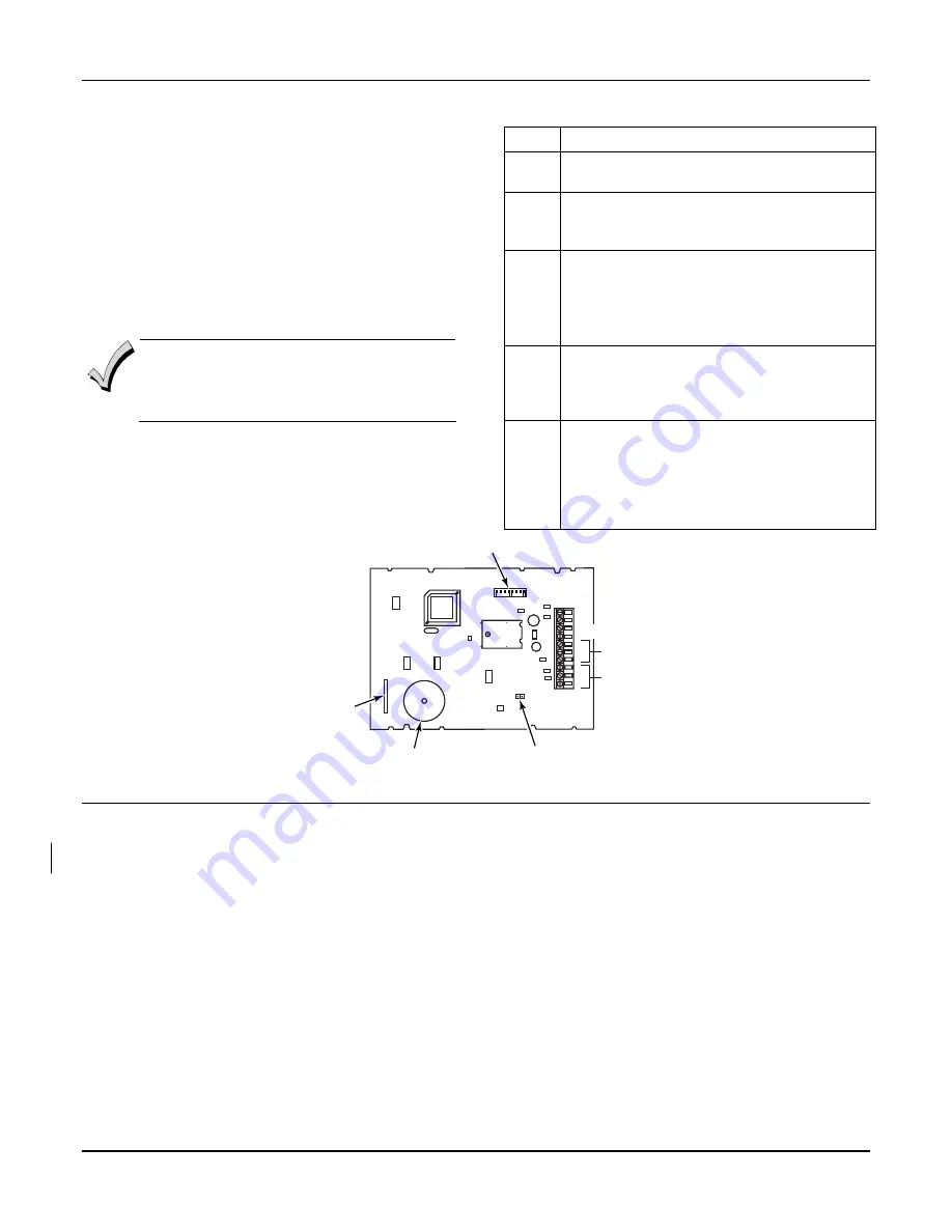
To mount and wire the Panel Link Module, refer to
Figure 3-27
and
perform the following steps:
Step Action
1
Remove all power from the control panel
before making any wiring connections.
2
Mount the module in the control cabinet if
space is available or, adjacent to the cabinet,
using 2-faced adhesive tape.
3
Set the PLM’s DIP switches for a device
address between 01 and 30. See the module’s
instructions for the DIP switch table.
Do not use an address being used by another
device (keypads, RF receivers, etc.).
4
Connect the 12V (+) and (–) and data-out and
data-in connections from the PLM to the
control’s keypads terminals (6, 7, 8, and 9),
respectively.
5
Connect the 3-wire RS-485 cable between
each PLM. Recommended wiring is to bring
the wires “in” from one module (or control
panel) to terminals 5 (+), 6 (-), and 7 (G) and
“out” to the next module from terminals TB1-
8 (+), 9 (-), and 10 (G).
+
_
G
+
_
G
+
_
1 2 3 4 5 6 7 8
PLG-002-V0
RS-485
RS-485
EOL
JUMPER
PINS
PIEZO
SOUNDER
TAMPER
REED
SWITCH
DIP
SWITCH
ECP IN
ECP OUT
Figure 3-27: VA8200 Panel Link Module Wiring
Event Log Printer Connections
This system has the ability to record up to 512 events of
various types in a history log (512 event capacity).
Each event is recorded in one of five categories with the
time and date of its occurrence (if real-time clock is set).
These categories are Alarm, Supervisory/Check,
Bypass, Open/Close, and System Conditions.
The log may be viewed (Display Mode) on an alpha
keypad, or can be printed (Print Mode) on a serial
printer (connected to the system via a 4100SM serial
interface module.
Printer Configurations
Printer must be configured as follows:
•
8 data bits, no parity, 1 stop bit
•
300 or 1200 baud (1200 preferred)
•
Hardware handshaking using DTR signal
•
The 4100SM module package includes a 3m RS232
cable. You can use a longer cable or an extension
cable if the Control and serial printer are separated
by more than 3m. The total cable length should be
less than 15m.
•
Most printers either ignore the CTS, DSR and CD
signals, or require them to be high (i.e. 3-15VDC as
measured on RS232 DB25 connector pins 5, 6 & 8
respectively with respect to ground pin 7). The
4100SM module sets these pins high. If the printer
does not operate with these pins high, then clip the
blue (CTS), white (DSR) or red (CD) jumpers on the
4100SM module to set the corresponding signal
floating. Important pins on the RS232C cable are
pin 3 (data out), pin 7 (ground) and pin 20 (DTR -
ready).
Summary of Contents for ADEMCO VISTA-120
Page 2: ...ii ...
Page 18: ...VISTA 120 Installation and Setup Guide 2 8 ...
Page 70: ...VISTA 120 Installation and Setup Guide 5 16 ...
Page 88: ...VISTA 120 Installation and Setup Guide 7 4 ...
Page 90: ...VISTA 120 Installation and Setup Guide 8 2 ...
Page 100: ...VISTA 120 Installation and Setup Guide A 2 ...
Page 104: ......
Page 106: ......
Page 113: ......


