


44 | EngliSH
3.3.5. Pump housing
The pump housing, depending on the model, is supplied
with different connections. This means that the machine
can be connected with the respective pipe system. The
pump housing is also available rubber-coated inside.
Some pump housings are supplied with a cleaning hole lid
to eliminate blockages.
The pump can equipped with a stationary wear ring which
can be found in the intake port. This wear ring determines
the gap between the impeller and the intake port. If this
gap is too big, the performance of the pump decreases
and it can lead to blockages. The rings can be changed to
minimize wear and expenses for spare parts.
3.3.6. Impeller
The impeller is fastened directly to the motor shaft and
driven by it. The impeller is also available in different ma-
terials (GG, GGG, VA, BZ) or coated with ceramic liquid.
A range of different impeller designs are available:
M:
Enclosed single channel impeller, for liquids containing
impurities and sludge with solid particles or long fibres.
K:
Enclosed multi channel impeller, for liquids containing
impurities and sludge with solid particles.
V:
Vortex impeller, for liquids containing a high level of impurities
or fibrous matter and containing gas.
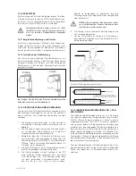
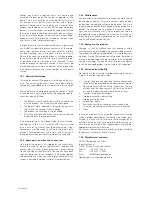
Direction of rotation control
All pumps run in the correct direction of rotation when
connected to a clockwise rotating field (U, V, W -> L1, L2,
L3). HOMA switchgears check the grid for a clockwise
rotating field. If there is no clockwise rotating field, the
red LED is lit. Two phases are to be exchanged at the
input to the switchgear. With smaller pumps, the check
can be made by observing the starting jerk. For this pur-
pose, place the pump perpendicular to the floor, slight-
ly on edge, and switch on briefly. Seen from above, the
pump jerks slightly anticlockwise if the direction of rota-
tion is correct. The direction of rotation of the pump is
correct if the pump moves anticlockwise because, seen
from above, the motor starts in the clockwise direction.
ST
AR
T
REACTION
ROTOR
REACTION
ATTENTION
The
direction of rotation
is correct if the
impeller/propeller rotates
in a
clockwise
manner
when viewing down from
top of the placed unit
ATTENTION
The
start reaction
is
anti clockwise
With bigger pumps the check may be done by watching
the rotation of the impeller through the discharge or suc-
tion inlet. Switch the pump on and off and check the direc-
tion of rotation when the impeller rotates slowly.
Beware of rotating impeller!
The moving impeller can crush and sever limbs.
Never reach into the pump unit or the moving parts
during operation. Switch off the machine and let the
moving parts come to a rest before maintenance or
repair work!
Additional the direction of rotation can control by a “motor
& phase rotation indicator”, which must put on the motor
housing of the operating pump.
Seal condition sensors at pumps with oil chamber
•
Models without cooling jacket or model „U“ with
cooling jacket and open circuit cooling:
In case of water entering the oil chamber through the shaft
seals, the resistance will change. The electrical resistance
of the oil in the oil chamber is measured by 2 sensors. The
sensors must be connected by 2 wires (marked S1 and
S2) of the pump connecting cable in the control panel with
a tripping unit with galvanically separated safety circuit.
The tripping unit should have an adjustable sensitivity of 0
to 100 k
Ω
, standard setting is approx. 50 k
Ω
.
Cable connection seal condition sensors
The cable connecting chamber is controlled by two sen-
sors for entering of water. The sensors must be connect-
ed by 2 wires (marked S3 and S4) of the pump connecting
cable in the control panel with a tripping unit with galvani-
cally separated safety circuit.
Motor cooling
Motors for submerged operation are cooled by the sur-
rounding liquid.
3.3.4. Sealing
The sealing between pump and motor is carried out by
two separate mechanical shaft seals (silicon-carbide) in
tandem-arrangement. It is made of bearing cover and
pressure cover. It is filled with medical white oil. Separate
large oil chamber, lubricating and cooling the mechanical
seals, forming an extra safety and inspection element.
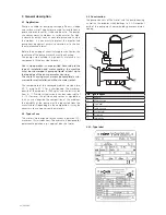
Summary of Contents for AM***-C
Page 1: ...Original Betriebsanleitung EN Original Instruction Manual AM X AV X C D C D 60 Hz ...
Page 35: ...DEUTSCH 35 Notizen Notes ...
Page 66: ...66 Notizen Notes ...
Page 67: ...67 Notizen Notes ...
Page 70: ...70 Notizen Notes ...
Page 71: ...71 ...


