


EngliSH | 43
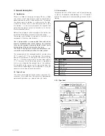
No.
Description
1
Manufacturer’s address
2
Motor type
3
Max. liquid temperature
4
Max. submersion
5
Protection class
6
No. of pump
7
Year of manufacture
8
Speed [min-1]
9
Insulation class
10
Frequency [Hz]
11
Weight [kg]
12
No. of phases
13
Motor input P1 / Motor output P2
14
Voltage [V]
15
Nominal current [A]
16
Cos
φ
17
Pump type
18
Max. Head
19
Min. Head
20
Max. Flow
21
FM approval with temperature code
22
Nema Code Letter
23
Motor output P2
3.3.2. Motor
The three-phase asynchronous motor is made from sheet
metal with a double-varnished winding wire as well as the
motor shaft with rotor package. The power supply cable is
designed for the maximum mechanical load and is sealed
against water pressure from the pumped liquid. The mo-
tor cable lead connections are sealed from the pumped
liquid as well. The bearings used are permanently lubri-
cated maintenance-free antifriction bearings. All models
are available with explosion proof motors according to FM
Class I, Division 1, Groups C & D.
General motor data
Service factor
1.15
Operating mode
S1
Max. liquid temperature
35°C / 95°F
Insulation class
H (180°C / 356°F)
Degree of ptotection
IP68
Cable length
10 m
Rotor shaft seal
Silicon-carbide / Silicon-carbide
mechanical shaft seal
Silicon-carbide / Silicon-carbide
Bearing
one grooved ball bearing
(above)
one double-row type angular
ball bearing (below)
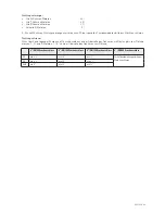
3.3.3. Control devices
The pump is equipped with various safety and control
devices:
Motor
Version
C...
Temperature monitoring in the winding
C.../C
Temperature monitoring in the winding , Oil chamber
seal conditions sensor
C...FM
Temperature monitoring in the winding , Explosion proof
C.../C FM Temperature monitoring in the winding , Oil chamber
seal conditions sensor, Explosion proof
D...
Temperature monitoring in the winding
D.../C
Temperature monitoring in the winding , Oil chamber
seal conditions sensor
D...FM
Temperature monitoring in the winding , Explosion proof
D.../C FM Temperature monitoring in the winding , Oil chamber
seal conditions sensor, Explosion proof
Temperature Sensors
The pumps have a set of temperature sensors built in the
stator windings.
Standard models have the sensors connected to the mo-
tor power supply cable, the wire ends marked T1 and T3.
They must be connected to the safety circuit of the con-
trol box in order to provide an automatic re-start of the
motor, when the motor cools.
Explosion proof models with motors up to 15 kW have a
set of temperature sensors built-in, with a higher switch-
off temperature, connected to the motor cable, the wire
ends marked T1 and T2. They must be connected to a
special relay in the starter box in order to provide manual
pump re-start.
All explosion proof models have both sets of sensors built-
in, as described above, with wire ends marked T1, T2,
T3. They have to be connected accordingly as described
above. The temperature sensor set must be connected to
the switchgear unit so that it switches off if it overheats.
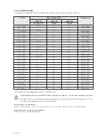
Switch-off temperature of the sensors:
Motor
Stator winding Normal
T1+T3 Regulator
Stator winding Ex
T1+T2 Limiter
AM122…C-2/4pol
140°C / 284°F
140°C / 284°F
AM136…D-2/4/6pol 140°C / 284°F
140°C / 284°F
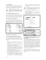
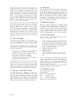
Check of Direction of Rotation
On original HOMA control boxes a control-light is illu-
minated, if the direction of rotation is not correct. With
smaller pumps the direction of rotation may be checked
by watching the start-jek. Put the pump vertical on the
ground and lift one edge. Start the motor. Viewed from
above, the unit must jerk anti-clockwise as the correct di-
rection of rotation is clockwise.
Summary of Contents for AM***-C
Page 1: ...Original Betriebsanleitung EN Original Instruction Manual AM X AV X C D C D 60 Hz ...
Page 35: ...DEUTSCH 35 Notizen Notes ...
Page 66: ...66 Notizen Notes ...
Page 67: ...67 Notizen Notes ...
Page 70: ...70 Notizen Notes ...
Page 71: ...71 ...


