Hobbico NexStar ARF Instruction Manual Download Page 21

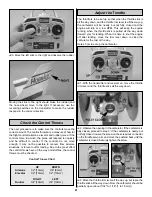
3. Move the left stick to the right and observe the rudder.

Moving the stick to the right should make the rudder (and
the nose wheel) move to the right. If necessary, use the
reversing switches on the transmitter to make the rudder
respond in the correct direction.

The next procedure is to make sure the controls move the
correct amount. The control throws are a measure of how far
the flight controls (ailerons, elevator and rudder) move. If the
controls move too much, the plane will respond too quickly
and be difficult to control. If the controls do not move
enough, it may not be possible to recover from adverse
situations or to level out for landing. Due to the great effect
the control throws have on the way a model flies, the control
throws must be checked.

Control Throws  Chart

The throttle is to be set up so that when the throttle stick is
all the way down, and the throttle trim lever is all the way up,
the carburetor will be nearly, but not fully closed and the
engine will idle at a low RPM. This will keep the engine
running when the throttle stick is pulled all the way down
(toward you) for landing. When it is time to shut the engine
off after landing, move the trim lever down to close the
carburetor the rest of the way.

Here’s how to set up the carburetor…

1. With the transmitter and receiver on, move the throttle

trim lever and the throttle stick all the way down.

2. Observe the opening in the carburetor. If the carburetor is

fully closed, proceed to step 3. If the carburetor is nearly, but
not fully closed, loosen the screw on the screw-lock connector
on the throttle servo arm and move the pushrod back until the
carburetor is closed. Securely tighten the screw.

3. Move the throttle trim lever all the way up, but leave the

throttle stick all the way down. Now the carburetor should be
partially open (about 1/32" to 1/16" [1 to 1.5mm]).

Adjust the Throttle

UP

DOWN

Ailerons

1/2" [13mm] 

3/8" [9mm] 

Elevator

1/2" [13mm] 

1/2" [13mm]

RIGHT

LEFT

Rudder

3/4" [19mm]

3/4" [19mm] 

Check the Control Throws

21

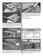
Summary of Contents for NexStar ARF

Page 1: ...reserves the right to change or modify this warranty without notice In that Hobbico has no control over the final assembly or material used for final assembly no liability shall be assumed nor accept...

Page 2: ...nder the guidance of an experienced flight instructor all you have to do is to concentrate on learning to fly And after you have mastered the NexSTAR your engine and radio may be transferred to your n...

Page 3: ...e throttle rudder and elevator and one servo in the wing for the ailerons This requires only a standard 4 channel radio The second option would be to use two servos in the wing one for each aileron Us...

Page 4: ...ems required to build the Hobbico NexSTAR ARF 1 Hobby knife HCAR0105 11 blades 5 pack HCAR0211 3 4 to 1 19mm to 25mm Heavy duty transparent tape Threadlocker thread locking cement GPMR6060 Small metal...

Page 5: ...ls 4 Engine mount 5 2mm Control rods 6 Wing joiner rods 7 IsoSmooth engine mount 8 11 x 5 280 x 127mm NexSTAR nylon propeller 9 Assembled fuel tank 10 2 1 2 64mm Spinner 11 Nose landing gear 12 1 4 20...

Page 6: ...Description How to purchase HCAA3736 Wing kit Local hobby dealer HCAA3737 Spin Control Airfoil Extensions Speed Brakes Local hobby dealer HCAA3738 Fuselage kit w o engine mount Local hobby dealer HCAA...

Page 7: ...and fin while tightening the tail bolts The tail bolts slide into blocks in the fuselage under the stabilizer As the tail bolts are tightened both the fin and stab are aligned and secured while streng...

Page 8: ...hat they do for your NexSTAR ARF They slow down the airplane increase its stall resistance and prevent it from spinning all desired characteristics of a trainer airplane The wing extensions can be rem...

Page 9: ...both wings following the scheme on the top of both wings Also apply the NexSTAR decal on the top of the left or right wing 4 Install the CenterCore wing rib on the right wing using two 4 x 3 4 19mm s...

Page 10: ...ogether 9 Cut and bend a 2mm x 6 150mm pushrod to match the sketch above Make a left and a right pushrod 10 Cut a servo arm as shown above and use a Hobbico Servo Horn Drill or a 48 or 5 64 2mm drill...

Page 11: ...e model will be difficult to trim Do not let anyone s opinion get in the way Install both these devices for your initial flights If after a few flights you decide to remove the extensions or flaps the...

Page 12: ...t them from coming loose with vibration 5 Install a clevis and a clevis retainer on the threaded end of the 17 1 2 445mm pushrod Bend the pushrod slightly as shown above to clear the engine mounting b...

Page 13: ...is running inspect it before running it again Check for cracks scuffled tips or unbalanced blades If necessary replace the propeller The Hobbico NexSTAR ARF was designed around an 11x5 propeller for b...

Page 14: ...bracket the steering arm and then the engine mount Tighten the screw on the steering arm 5 Install the nose wheel on the nose gear wire Use two wheel collars one on each side of the wheel to align it...

Page 15: ...installation is complete Note Should you ever need to remove the landing gear from the fuselage insert a screwdriver into the hole under the fuselage farther from the leg you want to remove Apply ligh...

Page 16: ...the bottom edge Note that one of the edges of the control horn is aligned with the hinge line of the rudder Mark the location of the control horn mounting holes Drill through the marks with a 1 16 1...

Page 17: ...r tighten these bolts 5 Connect both the elevator and rudder pushrod clevises to their control horns Use the second hole from the outer tip of the control horn for both of them This will allow you to...

Page 18: ...can also install a charge jack This will allow you to charge the batteries or check their voltage at the field without taking off the wing In the instruction manual airplane we installed an Ernst cha...

Page 19: ...nose wheel and tighten the steering s Screw Lock Pushrod Connector Move the throttle stick to full power and then fully open the carburetor by pushing on the throttle pushrod Make sure the throttle se...

Page 20: ...ons move the opposite way If the ailerons do not respond as described reverse the direction using the reversing switch for the aileron on the face of the transmitter If necessary refer to the instruct...

Page 21: ...all the way up the carburetor will be nearly but not fully closed and the engine will idle at a low RPM This will keep the engine running when the throttle stick is pulled all the way down toward you...

Page 22: ...t the wing to the fuselage with the nylon wing bolt Lift the model on both sides of the fuselage with your fingertips between the two lines on the bottom of the wing 4 If the fuselage is level when li...

Page 23: ...model within three miles of any pre existing flying site except in accordance with the frequency sharing agreement listed in the complete AMA Safety Code 9 Under no circumstances may a pilot or other...

Page 24: ...r inside your model 17 Cycle your receiver battery pack if necessary and make sure it is fully charged 18 If you wish to photograph your model do so before your first flight 19 Range check your radio...

Page 25: ...ly there may be a problem Do not fly the plane With the assistance of your instructor look for loose servo connections or binding pushrods Also be certain you are the only one on your frequency and th...

Page 26: ...ms so the plane flies straight and level After flying around for a while and while still at a safe altitude with plenty of fuel practice slow flight and execute practice landing approaches by reducing...

Page 27: ...ce The NexSTAR ARF was optimized to fly with the flaps on so if you remove them you will have to retrim the elevator Without flaps the NexSTAR ARF will try to pitch down nose down until you re trim it...

Page 28: ...leron control horn not included on the aileron as shown above Make sure you use thin CA to reinforce the holes in the aileron 5 Cut the servo arm as shown above Use a 6 152mm pushrod a clevis clevis r...

Page 29: ...n as shown above 4 Bend the second pushrod as shown above and connect it to the first with two 5 32 4mm wheel collars Tighten the two 6 32x1 4 6 4mm socket head cap screws to secure the two flap pushr...

Page 30: ...enerates when it picks up speed A trainer airplane such as the NexSTAR will still climb slightly at full power All airplanes need some right thrust and down thrust The right thrust angle for the NexST...

Page 31: ...31 Correct Angle Rods Fin...

Page 32: ...32...

Reviews: