


C21UE102-2110
83
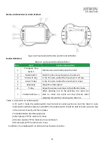
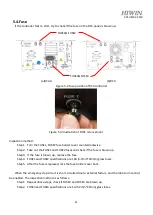
Names and functions on Teach Pendant
Figure 4-2 Teach pendant button position and definition
Button Definition:
Table 4-2 each pendant button definition
No.
Item
Function Description
1
Emergency Stop
Switch
Disable servo and directly stop the robot.
2
Mode Switch
Switch mode among manual, Auto and Lock
3
XY-Axis T1 Key
In the T1 mode, control the movement in XY-axis.
4
Z-Axis T1 Key
In the T1 mode, control the movement in Z-axis.
5
Speed Key
Adjust the robot speed
6
T1 Key
Adjust the value in each axis in the different mode.
7
Enable Switch
(Note 1)
When pressing one of the switches, the robot can
start to move; the robot will stop directly when
releasing this switch or pressing it to the end.
*Note 1: instruction on enable switch:
In T1 and T2 mode, the enable switch must be held at center position to start the robot. In Auto
mode (AUT) and External Auto mode (EXT), the enable switch should be held at center position only
in the moment it starts, and then release.
The Enable Switch has three positions:
(1) Not pressed
The robot can’t move.
(2) Center position
The robot can move and teach
(3) Fully pressed
The robot can’t move.
In addition, the enable switch on both side has the same function.
Summary of Contents for RC4
Page 1: ...www hiwin tw User Manual Robot Controller RC4 Series Original Instruction ...
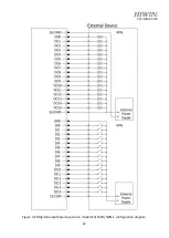
Page 64: ...C21UE102 2110 62 D SUB 44P INPUT NPN OUTPUT NPN ...
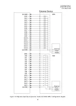
Page 65: ...C21UE102 2110 63 D SUB 44P INPUT PNP OUTPUT PNP ...
Page 77: ...C21UE102 2110 75 ...
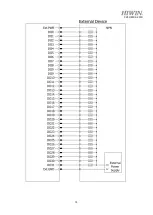
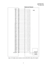
Page 79: ...C21UE102 2110 77 Figure 3 15 Digital output expansion model 32CH NPN configuration diagram ...
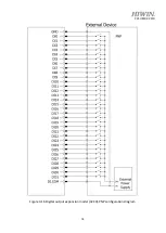
Page 80: ...C21UE102 2110 78 Figure 3 16 Digital output expansion model 32CH PNP configuration diagram ...


