background image


C21UE102-2110 

37 

Description: 

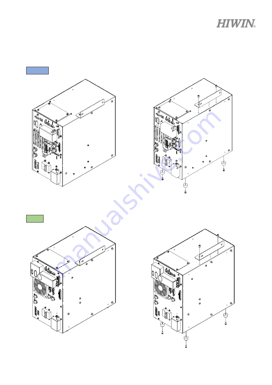
Place the controller upright, you must remove a fixed sheet metal part and replace the plastic foot 

from the bottom of the controller to the original side fixing point, as shown below. The plastic foot bolt is 
M4X0.7PX10L. 

  RC4-A


Figure 2-4 upright installed of RC4-A controller and plastic foot position replacement 


  RC4


Summary of Contents for RC4

Page 1: ...www hiwin tw User Manual Robot Controller RC4 Series Original Instruction ...

Page 2: ...n Semiconductor Medical Ball Type HG EG WE MG CG Quiet Type QH QE QW QR Other RG E2 PG SE RC Bearing Machine Tools Robot Crossed Roller Bearing Ballscrew Bearing Linear Bearing Support Unit DATORKER Robot Reducer Robot Automation Equipment Semiconductor Equipment Machine Tools WUT PO Type WUI CO Type WTI PH Type WTI AH Type AC Servo Motor Drive Semiconductor Packaging Machine SMT Food Industry LCD...

Page 3: ...ion Method 42 2 3 2 Transformer Installation Optional 45 2 4 Controller Boot Shutdown Program Description 47 2 5 Power and Signal Cable Connection 48 2 6 Emergency Stop Switch Connection E STOP optional 51 2 7 Remote Control Connect Description 56 3 External Input Output 58 3 1 Function I O 59 3 2 Digital I O 60 3 3 Example of Connection 61 3 4 RS 232 Port 65 3 5 RS 485 Port 67 3 6 External I O ex...

Page 4: ...h Pendant Description 82 4 2 Teach Pendant Connector Description 85 4 3 Teach Pendant Shortcut Connector 86 5 Maintenance and Inspection 87 5 1 Periodic Maintenance 87 5 2 Fan Filter 89 5 3 Confirmation of Robot System Operation 90 5 4 Fuse 91 5 5 Description of abnormal Industrial Computer System 93 5 6 Robot Controller Requirements Questionnaire 94 ...

Page 5: ...nuine HIWIN products 3 Adding or removing any components into out the product without authorized 4 Any modification of the wiring and the cable of the product 5 Any modification of the appearance of the product removal of the components inside the product e g remove the outer cover product drilling or cutting 6 Damage caused by any natural disaster i e fire earthquake tsunami lightning windstorms ...

Page 6: ...CS should conform to the requirement of performance level PL d and category 3 according to ISO 13849 1 6 The installation for emergency functions shall be defined by the system integrator in accordance with ISO 10218 1 ISO 10218 2 Safety Operation Principles 1 Before connecting the power supply for HIWIN industrial robot startup assembly procedure check whether the specification of factory output ...

Page 7: ...content description otherwise it will cause serious casualties Users must strictly abide by the content instructions otherwise it may cause minor injuries or equipment damage User must strictly abide by the content description otherwise it may cause poor product performance Use Limit Robotic arm is prohibited for use in the following environments and uses Personnel carrying purposes Explosive envi...

Page 8: ...ent according to safety regulations and puts it into operation The system integrator is responsible for the following tasks Install industrial robot arm Industrial machinery arm related equipment connection work Risk assessment of the overall system Use safe guard devices Confirm that the components used by the safe guard devices are in compliance with regulations Placement replacement setup opera...

Page 9: ...authority Mechanical arm maintenance work Operator Safety Precautions The manner and scale of the work and the possible hazards must be explained to the relevant personnel before work and relevant training courses must be carried out on a regular basis In the event of an accident or technical correction a training course must be re run System Set Up Safety Precautions The system set up only allows...

Page 10: ...at is protected by a safe guard device Please ensure the protective area includes working area of the robot A safety related part of control system SRP CS should conform to the requirement of Performance Level PL d and category 3 according to ISO 13849 1 Please ensure the emergency stop switch is in reset status before the robot functions The external device connected to the emergency stop switch ...

Page 11: ...C21UE102 2110 9 It must use EMO Emergency stop EN 60947 5 1 positive opening with safety module to meet ISO 13849 1 Performance Level PL d Interlock switch ...

Page 12: ...d within the protection area Do not damage or potentially damage the relevant equipment due to operates the robotic arm Operation must be carried out outside the protected area as much as possible Both manual and automatic modes of operation in the protected area are not permitted unless the arm is equipped with a certified speed monitoring accessory from the manufacturer Automatic Mode The automa...

Page 13: ...fences can be used during system installation and can be set according to ISO 10218 2 regulations Stop Functions Emergency Stop Description Emergency stop related precautions Confirm that the function is functioning normally every six months System integrators should provide emergency stop devices to ensure that the machine is operational or that a hazardous situation exists At least one external ...

Page 14: ...he weight of workpiece does not exceed the rated load or allowable load moment at wrist Exceeding these values could lead to the driver alarm or malfunction of the robot 8 Do not climb on manipulator 9 Do not store the machine in the environment with corrosion and flammable gas or close to the flammable object 10 Do not operate the machine in the environment with moisture water or grease 11 Do not...

Page 15: ...N OFF the power switch and the control button 12 Please ensure that the robot the emergency stop switch and the controller are functioning properly before performing any work 13 Do not shutdown the power switch during the operation 14 Do not open modify disassemble and maintain the machine without permission 15 The power must be disconnected when the machine does not operate in a long time 16 Do n...

Page 16: ...ce and repair should be performed by a qualified operator with a complete understanding of the entire system to avoid the risk of robot damage and personal injury 6 When replacing the components avoid foreign object going into the robot Precautions for using End Effector End effectors can be basically divided into the following two categories A Gripper Mainly for pick and place operations such as ...

Page 17: ... system integrator in accordance with the related standards Precautions for using Hydraulic and Pneumatic 1 When using the pneumatic or hydraulic system the gripped workpiece may fall due to insufficient pressure or gravity 2 The pneumatic or hydraulic system must be equipped with the relief valve so that it can be applied in an emergency 1 More attention should be paid to the pressure remained in...

Page 18: ...all operations are stopped and the control system of the robot arm is turned off 2 To resume execution reset the emergency stop switch 3 Emergency stop is immediate stop Immediately stop the movement of the robot arm and cut off the power of the drive 4 The emergency stop switch is for emergency stop only 5 HIWIN s industrial robot arm has two emergency stop switches one of which is located on the...

Page 19: ...bus RTU 1 Ethernet 2 USB 2 External I O signals standard Emergency stop Input 1 Function I O Input 8 Output 8 Digital I O Input 16 Output 8 Power Power source VAC Single phase 200 240 Power capacity KVA 3 3 Power frequency Hz 50 60 Voltage drop msec 10 or less Rating output current A 14 Current leakage mA 30 Weight kg 14 protection rating 23 Temperature range for workplaces 5 45 Relative humidity ...

Page 20: ...nt data 5000 Step number 10000 Teaching method Remote Communication interface RS232 1 RS485 1 Ethernet 1 USB 2 External I O signals standard Emergency stop Input 1 Function I O Input 8 Output 8 Digital I O Input 16 Output 8 Power Power source VAC Single phase 200 240 Power capacity KVA 1 65 Power frequency Hz 50 60 Voltage drop msec 10 or less Rating output current A 6 Current leakage mA 30 Weight...

Page 21: ...ual CH 5 2 2 Timing belt J4M RS405Z031 8 Refer to manipulator manual CH 5 2 2 Timing belt J4S RS405Z031 9 Refer to manipulator manual CH 5 2 2 Ball spline grease 1kg G04 RS405Z031 10 Refer to manipulator manual CH 5 2 3 Reducer grease 16kg G11 RS405Z031 11 Refer to manipulator manual CH 5 2 4 Base transfer plate RS405Z031 12 Refer to manipulator manual CH 2 6 RC4 Power Cable 3M RC4 A RC400C001 32 ...

Page 22: ... to manipulator manual CH 5 2 2 Timing belt J4S RS410071 9 Refer to manipulator manual CH 5 2 2 Ball spline grease 1kg G04 RS410071 10 Refer to manipulator manual CH 5 2 3 Reducer grease 16kg G11 RS410071 11 Refer to manipulator manual CH 5 2 4 Base transfer plate RS410071 12 Refer to manipulator manual CH 2 6 RC4 Power Cable 3M RC4 A RC400C001 32 Refer to CH 2 3 RC4 RC400C001 1 Accessory Kit RC4 ...

Page 23: ...Connector 44P RC400C001 6 1 Fuse 10A Fuse1 2 RC400C001 7 2 Fuse 3A Fuse3 4 RC400C001 26 2 Fan Filter RC400C001 33 2 E STOP Connecter RC400C001 30 1 RC4 Accessory kit RC400C001 2 Item HIWIN Part No Quantity D SUB Connector 15P RC400C001 3 1 Housing of D SUB Connector 15P RC400C001 4 1 High Density D SUB Connector 44P RC400C001 5 1 Housing of High Density D SUB Connector 44P RC400C001 6 1 Fuse 10A F...

Page 24: ... RC400C001 19 RC400C001 20 Refer to CH 3 6 3 Digital Output Expansion Module 32ch Ethernet Cable 3m Cable grommet RC400C001 21 RC400C001 18 RC400C001 19 Refer to CH 3 6 4 註2 Digital Input Expansion Module 32ch Ethernet Cable 3m Cable grommet RC400C001 22 RC400C001 18 RC400C001 19 Refer to CH 3 6 5 註2 Digital I O Expansion Module 16DI 16DO Ethernet Cable 3m Cable grommet RC400C001 23 RC400C001 18 R...

Page 25: ...nsions RC4 A The following below shows appearance dimensions of RC4 A Unit mm Figure 1 1 appearance dimensions of RC4 A controller As a completed installation dimension some space needs to be reserved for the cables Please refer to CH2 1 ...

Page 26: ... The following below shows appearance dimensions of RC4 Unit mm Figure 1 2 appearance dimensions of RC4 controller As a completed installation dimension some space needs to be reserved for the cables Please refer to CH2 1 ...

Page 27: ...e Motor Signal Connect controller to the robot manipulator 4 Power Connector Cable Motor Power Connect controller to the robot manipulator 5 Network Connector Ethernet signal transmission 6 USB Connector USB signal transmission 7 RS232 Connector RS232 signal transmission 8 RS485 Connector RS485 Modbus RTU signal transmission 9 Emergency Stop Connector Connect to external emergency stop device 10 I...

Page 28: ...nnector Cable Motor Signal Connect controller to the robot manipulator 4 Power Connector Cable Motor Power Connect controller to the robot manipulator 5 Network Connector Ethernet signal transmission 6 USB Connector USB signal transmission 7 RS232 Connector RS232 signal transmission 8 RS485 Connector RS485 signal transmission 9 Emergency Stop Connector Connect to external emergency stop device 10 ...

Page 29: ...lamp indicator lamp situations refer to Table 1 7 RC4 A a RC4 A Figure 1 4 Indicator lamp appearance of RC4 A controller Table 1 5 Indicator light situation description Situation White lamp Green lamp Yellow lamp Red lamp Remark Turn on process pushed emergency stop switch white lamp flashing cycle time two seconds Enter HRSS system Clear error emergency stop Execute program Stop program Pushed em...

Page 30: ...h moisture with high temperature under direct sunlight or potentially explosive environment Please keep the controller away from the strong electric field or the magnetic field The rear side of the controller is provided with a heat dissipation hole please make sure that there is 100mm of heat dissipation space behind the controller Please place the controller flat and stable and avoid shock or vi...

Page 31: ...C21UE102 2110 29 1 7 Sticker and Label RC4 A The following shows the appearance stickers and labels of RC4 A controller Figure 1 5 the appearance stickers and labels of RC4 A controller ...

Page 32: ... specification of RC4 A controller Table 1 6 the appearance stickers and labels of RC4 A controller 1 Controller specification 2 Beware of electric shock 3 Grounding 4 Transport by multiple people 5 Danger authorized proffesionals only 6 Tamper seal sticker ...

Page 33: ...C21UE102 2110 31 RC4 The following shows the appearance stickers and labels of RC4 controller Figure 1 7 the appearance stickers and labels of RC4 controller ...

Page 34: ...of RC4 A controller Table 1 10 the appearance stickers and labels of RC4 A controller No Illustration Description 1 Controller specification 2 Beware of electric shock 3 Grounding 4 Transport by multiple people 5 Danger authorized proffesionals only 6 Tamper seal sticker ...

Page 35: ...can be set to planar and upright For ease of maintenance and ventilation around the controller please set it as shown Planar RC4 A It is recommended to reserve 240mm outlet space in front of the RC4 A controller panel Figure 2 1 Planar installed of the RC4 A Controller figure ...

Page 36: ...C21UE102 2110 34 RC4 It is recommended to reserve 150mm outlet space in front of the RC4 controller panel Unit mm Figure 2 2 Planar installed of the RC4 Controller figure ...

Page 37: ...C21UE102 2110 35 Upright RC4 A It is recommended to reserve 235mm outlet space in front of the RC4 A controller panel Figure 2 2 Upright installed of the RC4 A Controller figure ...

Page 38: ...o reserve 150mm outlet space in front of the RC4 controller panel Unit mm Figure 2 3 Upright installed of the RC4 Controller figure Refer to the above method for controller placement Do not reverse 180 degree and ensure the installation pitch ...

Page 39: ...ve a fixed sheet metal part and replace the plastic foot from the bottom of the controller to the original side fixing point as shown below The plastic foot bolt is M4X0 7PX10L RC4 A Figure 2 4 upright installed of RC4 A controller and plastic foot position replacement RC4 ...

Page 40: ...eplace plastic foot position Controller heat dissipation RC4 A Figure 2 6 RC4 A controller heat dissipation RC4 Figure 2 7 RC4 controller heat dissipation The temperature of the air vent of the controller is high Do not install a heat resistant device at the air vent ...

Page 41: ...ers The fix sheet metal can be assembled above the controller and used as a handle sheet metal for transportation purposes The installation method is shown in the figure below The bolt used is M5X0 8PX6L RC4 A Figure 2 8 RC4 A multi function handler up fixed RC4 Figure 2 9 RC4 multi function handler up fixed ...

Page 42: ... can be assembled under the controller to position the controller as a lock The installation method is as shown below RC4 A Figure 2 10 RC4 A multi function handler down fixed RC4 Figure 2 11 RC4 multi function handler down fixed ...

Page 43: ... multi function handler Unit mm RC4 A Figure 2 12 RC4 A corresponding size of multi function handler RC4 Figure 2 13 RC4 corresponding size of multi function handler In order to fix to the gantry thread the hole according to the size shown ...

Page 44: ...s must be used The power can be turned on and tested after connecting the main components mentioned below Please make sure that the grounding of manipulator must connected to the power grounding directly Robot controller must to connect compliant with electricity leakage breaker below 30mA avoiding operators make leakage current damage RC4 A Figure 2 14 Robot with RC4 A controller connection Table...

Page 45: ...r connection Table 2 2 corresponding number of RC4 controller system structure No Basic connection structure 1 Main Power Cable 2 Power Cable 3 Signal Cable 4 Emergency Stop Switch 5 Robot arm ground wire Note Note Please prepare the UL1015 16AWG ground wire ...

Page 46: ... no risk of electric shock after turning off the power Be sure to connect the ground wire of the power cable to the ground of the power box Controller power cable connection 1 Remove protective cover 2 Connect the power cable 3 Use retaining strap to hold the wire 4 Cover the protective cover and lock it Define Color L Red N White Ground Green Ground Green N White L Red ...

Page 47: ...roller is single phase 220V 4KVA If the power supply voltage specifications of the client are different the transformer can be used in series The installation can refer to the dimensions below Unit mm It is recommended to reserve 360mm space on the front of the cabinet so that the door can be opened and pay attention to the cooling space of the rear fan ...

Page 48: ...ation is single phase 220V If the power supply specifications of the client are different the transformer must be connected in series Before running for a test please make sure that the manipulator is securely installed to prevent from tipping during the motion ...

Page 49: ...he power switch off Operator must not leave until the power switch is switched off If the above process is not completed do not directly switch off the power switch or the main power switch on the controller If the power is off the controller may be damaged Do not turn the power back on immediately after turning off the power switch Wait 30 seconds before turning the power on In order to stop the ...

Page 50: ...en connecting This connector has directionality If it cannot be inserted please convert it to 180 degrees and insert it again 3 After the connection is completed use the fixed buckle to hold the wire as shown in the right figure 4 Assemble the protective cover back and secure the screw Manipulator signal cable connection 1 The signal cable is a 25P D sub connector This connector has directionality...

Page 51: ...he power supply cable is a 20P double row rectangular connector Pay attention to the connector label when connecting This connector has directionality If it cannot be inserted please convert it to 180 degrees and insert it again 3 After the connection is completed use the fixed buckle to hold the wire as shown in the right figure 4 Assemble the protective cover back and secure the screw Manipulato...

Page 52: ... serial number on the controller label because each controller saves the setting parameters of a specific robot If the connection is wrong it may result in abnormal system issues damages even unpredictable hazards It is prohibited to connect a robot to another controller even with the same model ...

Page 53: ...rgency stop device configuration 1 Emergency stop device configuration must to double loop designed 2 After touched emergency stop device double loop need to broke and then returned to meet the safety design ISO13849 1 EN62061 RC4 A attention of Controller emergency stop device configuration 1 Emergency stop device configuration must to double loop designed 2 After touched emergency stop device bo...

Page 54: ...y circuit abnormal When safety circuit abnormal please to cut off both double loop after enter emergency stop on state clear error alarm and returned The emergency stop device must be connected to the controller and be placed at the position accessible to the operator and any signal or power source should not come into contact with any metal enclosure Incorrect method of using can cause a severe d...

Page 55: ...ted Connect the D SUB connector to the E STOP interface and securely lock the connector to the panel RC4 A RC4 Please ensure this emergency stop switch and the emergency stop on the teach pendant are in reset status The external device connected to the emergency stop switch circuit should be dry contact uncharged switch It is forbidden to use a live circuit to connect to the controller emergency s...

Page 56: ...C21UE102 2110 54 Figure 2 16 EMO Emergency stop circuit of controller It must use EMO Emergency stop EN 60947 5 1 positive opening with safety module to meet ISO 13849 1 Performance Level PL d ...

Page 57: ...C21UE102 2110 55 Interlock switch Figure 2 17 Robot safety fence and Interlock switch Safety protected device must have double channels which meets ISO 13849 1 performance level PL d ...

Page 58: ...ontrol Connect Description Remote control connect description refer to below Figure 2 18 Illustration of remote control connect Note Software operator refers to Caterpillar user manual Remote operate interface software user manual ...

Page 59: ...etwork cable connection refers to below RC4 A Both LAN ports of RC4 A controller can be used Figure 2 28 1 RC4 A controller network connection RC4 RC4 controller only one LAN port can use Figure 2 28 2 RC4 controller network connection ...

Page 60: ...nal I O wiring set optional equipment can be used to include the cable and terminal block The connector accessary kit contains the D SUB 44P solder connector There are two types of controller external I O 1 Function I O FI O specific function I O 2 Digital I O DI O external I O for customer s configuration Figure 3 1 Definition of D SUB 44PIN ...

Page 61: ... request 1 program selection 1 7 RSR2 PNS2 Robot service request 2 program selection 2 8 RSR3 PNS3 Robot service request 3 program selection 3 9 RSR4 PNS4 Robot service request 4 program selection 4 OUTPUT Pin Parameter Function 10 RUN Program running 11 HELD Program pausing 12 FAULT Controller failure 13 READY Controller ready 14 ACK1 SNO1 RSR 1 feedback signal selection program No 1 25 ACK2 SNO2...

Page 62: ...nector Digital I O List Table 3 2 Definition of Digital I O DI O pin of controller D SUB 44P Pin Parameter Pin Parameter 17 DI 1 33 DI 11 18 DI 2 34 DI 12 19 DI 3 35 DI 13 20 DI 4 36 DI 14 21 DI 5 37 DI 15 22 DI 6 38 DI 16 23 DI 7 39 DO 3 24 DI 8 40 DO 4 28 DO 1 41 DO 5 29 DO 2 42 DO 6 31 DI 9 43 DO 7 32 DI 10 44 DO 8 ...

Page 63: ... COM and pin 16 DI COM supplied by an external power supply COM 24V NPN COM 0V PNP 2 Digital OUTPUT can be an NPN or PNP adjusted by pin 15 FO COM and pin 30 DO COM supplied by an external power supply COM 0V NPN COM 24V PNP The maximum current at the single output supplied by external output is 100mA ...

Page 64: ...C21UE102 2110 62 D SUB 44P INPUT NPN OUTPUT NPN ...

Page 65: ...C21UE102 2110 63 D SUB 44P INPUT PNP OUTPUT PNP ...

Page 66: ...cted Plug in the connector and secure the screw indeed RC4 A RC4 No signal or power supply should be close to or in contact with any metal case Incorrect method of using can cause a severe damage or loss of life and property To prevent the internal components from damage any wiring operation must be done only when the controller is disconnected Please make sure the screws on the connector are secu...

Page 67: ...S 232 controller Figure 3 2 RS 232 connector of controller Table 3 3 Definition of RS 232 pin Pin Description 2 RXD Receiver 3 TXD Transmit 5 GND Ground The following figure shows the connection method with external device Controller External Device Figure 3 3 RS 232 wiring diagram of controller ...

Page 68: ...d Plug the connector in and secure the screw indeed RC4 A RC4 No signal or power supply should be close to or in contact with any metal case Incorrect method of using can cause a severe damage or loss of life and property To prevent the internal components from damage any wiring operation must be done only when the controller is disconnected Please make sure the screws on the connector are secured...

Page 69: ...ment of RS 485 controller Modbus RTU Figure 3 4 RS 485 connector of controller Table 3 4 Definition of RS 485 pin PIN Description 1 Data 2 Data The following figure shows the connection method with external device Controller External Device Figure 3 5 RS 232 wiring diagram of controller ...

Page 70: ...d Plug the connector in and secure the screw indeed RC4 A RC4 No signal or power supply should be close to or in contact with any metal case Incorrect method of using can cause a severe damage or loss of life and property To prevent the internal components from damage any wiring operation must be done only when the controller is disconnected Please make sure the screws on the connector are secured...

Page 71: ...ROFINET or ETHERNET IP select one Install cable grommet and EtherCAT cable Expansion module 32 channel DO module 32 channel DI module 16DI 16DO module Encoder data acquisition module CC Link connector PROFINET or ETHERNET IP select one Install cable grommet and EtherCAT cable Expansion module 32 channel DO module 32 channel DI module 16DI 16DO module Encoder data acquisition module CC Link connect...

Page 72: ...in assignment of CC LINK controller a RC4 A b RC4 Figure 3 8 CC LINK connector of RC4 controller Figure 3 9 Illustration of CC LINK connector and pin define Table 3 5 Definition of CC LINK pin Pin Signal Description 1 DA Data A 2 DB Data B 3 DG Data Ground 4 SLD Shield 5 FG Field Ground CC Link ...

Page 73: ... IP 連接器位置圖 Figure 3 11 illustration of PROFINET pin number Table 3 6 Definition of PROFINET pin Pin Signal Description 1 TX Transmit Data 2 TX Transmit Data 3 RX Receive Data 4 Term 1 Connected to each other and terminated to PE through RC circuit 5 Term 1 6 RX Receive Data 7 Term 2 Connected to each other and terminated to PE through RC circuit 8 Term 2 PROFINET or ETHERNET IP select one ...

Page 74: ... definition is shown below Use an incremental rotary encoder with differential output signal Table 3 7 Encoder data acquisition module data Signal Description F G Frame Ground GND Power supply Ground 0V Vs Power supply 24VDC IN EtherCAT signal input OUT EtherCAT signal output Figure 3 12 Encoder data acquisition module dimensions and pin definition ...

Page 75: ...on Channel A0 Encoder input A0 Channel 0 A0 Encoder input A0 B0 Encoder input B0 B0 Encoder input B0 C0 24 VDC C0 Latch NPN out A1 Encoder input A1 Channel 1 A1 Encoder input A1 B1 Encoder input B1 B1 Encoder input B1 C1 24 VDC C1 Latch NPN out A2 Encoder input A2 Channel 2 A2 Encoder input A2 B2 Encoder input B2 B2 Encoder input B2 C2 24 VDC C2 Latch NPN out ...

Page 76: ...el signal data Signal Description F G Frame Ground GND Power supply Ground 0V Vs Power supply 24VDC IN EtherCAT signal input OUT EtherCAT signal output Figure 3 13 Digital output expansion model 32CH dimensions and pin define The number of expansion modules and the number of I O channels can be changed flexibly so the DI DO number on the device and the DI DO number on the software interface will b...

Page 77: ...C21UE102 2110 75 ...

Page 78: ... supply Ground 0V Vs Power supply 24VDC IN EtherCAT signal input OUT EtherCAT signal output Figure 3 14 Digital input expansion model 32CH dimensions and pin definition Digital INPUT can be an NPN or PNP adjusted by DI COM supplied by an external power supply COM 24V NPN COM 0V PNP The number of expansion modules and the number of I O channels can be changed flexibly so the DI DO number on the dev...

Page 79: ...C21UE102 2110 77 Figure 3 15 Digital output expansion model 32CH NPN configuration diagram ...

Page 80: ...C21UE102 2110 78 Figure 3 16 Digital output expansion model 32CH PNP configuration diagram ...

Page 81: ...sion model signal data Signal Description F G Frame Ground GND Power supply Ground 0V Vs Power supply 24VDC IN EtherCAT signal input OUT EtherCAT signal output Figure 3 17 Digital output input expansion model 16 16CH dimensions and pin definition The number of expansion modules and the number of I O channels can be changed flexibly so the DI DO number on the device and the DI DO number on the soft...

Page 82: ...C21UE102 2110 80 Figure 3 18 Digital output input expansion model 16 16CH NPN 1 configuration diagram ...

Page 83: ...C21UE102 2110 81 Figure 3 19 Digital output input expansion model 16 16CH NPN 2 configuration diagram ...

Page 84: ...ion for user s safety the Teach Pendant is equipped with the Emergency Stop Switch and the Enable Switch Figure 4 1 Teach pendant appearance Specification Table 4 1 Teach pendant specification Item HIWIN Robot Teach Pendant Model No TP02 Dimensions 318x245x107 mm3 Weight 2 5kg Protection Rating IP20 Display 10 2 touch screen Resolution 1024x768 pixels Mode Manual Auto and Lock Physical Button 20ke...

Page 85: ...he value in each axis in the different mode 7 Enable Switch Note 1 When pressing one of the switches the robot can start to move the robot will stop directly when releasing this switch or pressing it to the end Note 1 instruction on enable switch In T1 and T2 mode the enable switch must be held at center position to start the robot In Auto mode AUT and External Auto mode EXT the enable switch shou...

Page 86: ...It is forbidden to use Teach Pendant in the high dust concentration and high grease concentration environment since its protection rating is IP20 To ensure the Teach Pendant functions normally any impact and fall are forbidden ...

Page 87: ...e When using teach pendant of RC4 A controller need to notice below Before inserting need to check two side connector corresponding to the cusp of the triangle mark teach pendant connector HRS word face up side a Teach pendant triangle mark position b Front right way c under side wrong way Figure 4 3 Teach pendant connector connect of RC4 A controller ...

Page 88: ... teach pendant please insert the Teach Pendant Shortcut Connector into the CN4 connector Please shutdown the controller power when removing the teach pendant and inserting the shortcut connector Teach pendant shortcut connector with controller description Please insert the Teach Pendant Shortcut Connector into the CN4 connector Please align the arrow mark and buckle the safety lock authentically ...

Page 89: ...ecute maintenance task avoid to operator electric shock or robot non normal motion situation 5 1 Periodic Maintenance The daily inspection items before the robot operation are shown below Table 5 1 Daily Inspection Items Inspection item Remedy Before turning power on Are all the cables securely connected Such as the power and signal cable grounding cable the cable for teach pendant and the cable c...

Page 90: ...onths Item A Item B 72 months Item A Item B Inspection items Remedies Inspection item A 3 months 960 hours Is there fan cotton filter dirty or dust accumulated Inspection time only to refer it need to depend on work environment state time maybe advance or delay If severely dirty and blocked please replace by yourself Inspection item B 3 years 11520 hours Check fan is turning normal Firstly clean t...

Page 91: ...cing the filter depends on the working environment Step1 Remove the fan filter cover Step2 Replace the internal filter Step3 Mount the fan filter cover RC4 A RC4 a RC4 A b RC4 Figure 5 1 Illustration of fan filter replacement of controller The accumulation of foreign matter causing internal filter experiencing poor convection This may cause the inner controller occurring over temperature and contr...

Page 92: ...e The robot arm is energized and the LED status is maintained to be steady 5 Execute the Manual or Auto mode and confirm that the robot arm is operating normally without vibration or abnormal sound When checking the operation check that there is no setting or wiring error If the robot arm performs an abnormal operation due to a setting or wiring error immediately press the emergency stop switch to...

Page 93: ...USE2 fuses and check if the fuse is blown up Step3 If the fuse is blown up replace the fuse Step4 FUSE1 and FUSE2 specifications are 10A 5 2mm 20mm glass fuses Step5 After the fuse is replaced lock the fuse holder cover back When the emergency stop circuit is short circuited due to external factors and the robot arm cannot be enabled The inspection method is as follows Step1 Repeat above steps che...

Page 94: ...C21UE102 2110 92 The fuse replacement must be operated with the controller switched off Do not replace fuses with different amperages or replace fuses with other conductive materials wire iron ...

Page 95: ...l or dealer perform maintenance HRSS and Caterpillar software time interface below Figure 5 4 HRSS software time interface Figure 5 5 Caterpillar software time interface If the software time and the current time are abnormal please operates the software to adjust time setting in the controller refers to HRSS or Caterpillar software manual If finished to time setting and after restarted robot there...

Page 96: ...ed Movement Horizontal Motion Range _______ mm Vertical Motion Range _________ mm Repeatability _________ mm Cycle Per Minute __________ CPM Installation Input Power Single Phase 220 V Three Phase 380V 415V 480V 575V please select Length of Floor Cable 2m Standard 5m Option 10m Option Communication Standard TCP IP Modbus TCP RS 232C 8IN 8OUT Function I O 16IN 8OUT Digital I O Option CC Link PROFIN...

Page 97: ...0 200 400 LU please select Remark Note 1 For Palletizing application need to provide pallet type and space planning Note 2 For polishing visual pick and place application need to provide work part or 3D model and photo of comparison before and after Note 3 For dynamic tracking application please description as dynamic pick dynamic place vision recognition sensor acquisition and provide real produc...

Page 98: ...te for patented product directory http www hiwin tw Products Products_patents aspx 4 HIWIN will not sell or export products or processes restricted under the Foreign Trade Act or related regulations Export of restricted products should be approved by proper authorities in accordance with relevant laws and shall not be used to manufacture or develop nuclear biochemical missiles or other weapons Pub...

Page 99: ...HIWIN CHINA SUZHOU CHINA www hiwin cn info hiwin cn Mega Fabs Motion Systems Ltd HAIFA ISRAEL www mega fabs com info mega fabs com HIWIN GmbH OFFENBURG GERMANY www hiwin de www hiwin eu info hiwin de HIWIN JAPAN KOBE TOKYO NAGOYA NAGANO TOHOKU SHIZUOKA HOKURIKU HIROSHIMA FUKUOKA KUMAMOTO JAPAN www hiwin co jp info hiwin co jp HIWIN USA CHICAGO U S A www hiwin us info hiwin com HIWIN Srl BRUGHERIO ...

Reviews: