


5-1
5.
Print head-related maintenance
5.1 Outline structure of print head and how to remove each cover
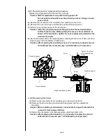
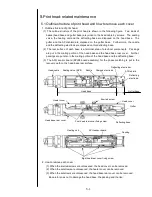
1. Outline structure of print head
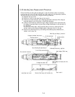
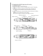
(1) The outline structure of the print head is shown in the following figure. Two kinds of
bases (head base and gutter base) are joined to the head cable by screws. The sealing
valve, the heating unit and the deflecting base are disposed on the head base. The
gutter and the APH shield are disposed on the gutter base. Furthermore, the nozzle
and the deflecting electrode are disposed on this deflecting base.
(2) The rear surface of each base is a terminal area of electrical components. Packings
are put in the mating portion of the head base and the head base rear cover. Further,
packings are put also in the mating portion of the head base and the deflecting base.
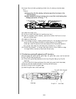
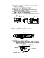
(3) The APH sensor board (EZJ98 board assembly) for the phase matching is put in the
recovery path on the head base rear surface.
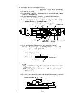
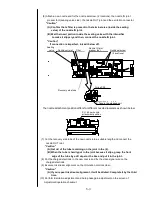
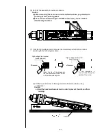
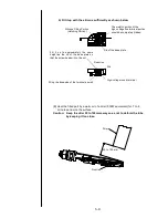
2. How to remove each cover
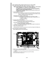
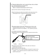
(1) When the knurled screws are unloosened, the head cover can be removed.
(2) When the setscrews are unloosened, the heater cover can be removed.
(3) When the setscrews are unloosened, the head base rear cover can be removed.
Be careful so as not to damage the head base, the packing and the like.
Sealing valve (MV9)
Heating unit
Head cable
Charged electrode
Deflecting
electrode-
Deflecting el
Nozzle
Gutter
Head base
Gutter base
APH shield
Deflecting base
Head base rear cover
APH sensor board
Heater cover
Head cover
Packing
Knurled screw
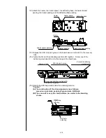
Four head rear cover fixing screw
Eight head rear cover fixing screw
Summary of Contents for IJ PH
Page 1: ...Service Manual HITACHI Printer Model PH Revision Aug 2011 Version First edition ...
Page 2: ... Revision of PH service manual Revision Chapter Revised Page ...
Page 13: ...1 2 2 Main body internal PH D 1 8 ...
Page 80: ...3 25 3 25 Circuit diagram of EZJ95 ...
Page 201: ...7 1 7 Attached Drawing 7 1 Circulation System Diagram ...
Page 202: ...7 2 7 2 Electrical Connection Diagram ...
Page 205: ...7 5 7 4 Dimensions around charge electrode and deflection electrode Nozzle diameter 65 um ...


