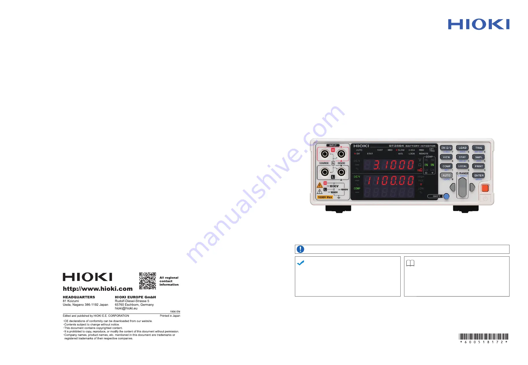
Hioki BT3564 Instruction Manual Download Page 1

BT3564

Instruction Manual

BATTERY HiTESTER

EN

Oct. 2020  Revised edition 2

BT3564A961-02  20-10H

Be sure to read this manual before using the instrument.

  p.3

When using the instrument for the 

first time

Troubleshooting

Names and Functions of Parts


p.9

Maintenance and Service

  p.173

Measurement

  p.21

Troubleshooting

  p.173

Error Indication

  p.175

HIOKI BT3564A961-02

Summary of Contents for BT3564

Page 1: ...961 02 20 10H Be sure to read this manual before using the instrument p 3 When using the instrument for the first time Troubleshooting Names and Functions of Parts p 9 Maintenance and Service p 173 Me...

Page 2: ...HIOKI BT3564A961 02...

Page 3: ...necting the Optional Test Leads 17 2 4 Turning the Power On and Off 18 2 5 Selecting the Line Frequency 20 Chapter 3 Measurement ______________________________ 21 3 1 Pre Operation Inspection 21 3 2 B...

Page 4: ...hing Between Measurement Value and Comparator Setting Displays 56 4 2 Trigger Function 57 Trigger Source Settings 57 Trigger Delay Settings 58 4 3 Averaging Function 59 4 4 Statistical Calculation Fun...

Page 5: ...l 98 Attaching the Connector 98 Selecting the Communication Conditions 100 8 4 Communication Methods 101 Message Format 101 Output Queue and Input Buffer 105 Status Byte Register 106 Event Registers 1...

Page 6: ...for Making Custom Test Leads A 1 Appendix 2 AC Four terminal Method A 4 Appendix 3 Measurement values when using four terminal measurement Differences in measurement values due to measurement leads us...

Page 7: ...is manual has been written for use by individuals who use the product in ques tion or who teach others to do so It is assumed that the reader possesses basic electrical knowledge equivalent to that of...

Page 8: ...your authorized Hioki distributor or reseller when ordering The options are subject to change Visit our website for updated information Model L2110 Pin Type Lead 1000 V DC or less Model L2100 Pin Type...

Page 9: ...symbol printed on the instrument indicates that the user should refer to a corresponding topic in the manual marked with the symbol before using the relevant function Indicates a prohibited action p...

Page 10: ...surface Usage Notes To avoid electric shock do not remove the instrument s case The internal com ponents of the instrument carry high voltages and may become very hot during operation Avoid using near...

Page 11: ...touch the metallic tip of probes after measuring high voltage batteries Doing so may result in electrical shock since internal instrument components could retain a charge under those conditions Intern...

Page 12: ...ower If the power supply frequency is not set properly measurements will be unstable See 2 5 Selecting the Line Frequency p 20 Make sure the power is turned off before connecting or disconnecting the...

Page 13: ...four terminal 1 kHz AC method while simultaneously measuring DC voltage electromotive force emf The high precision fast measurement performance and extensive interface capabilities make these models...

Page 14: ...correct recognition of judgment results Statistical Calculation Functions Maximum minimum and average of the measurement values standard devia tion process capability indices and other values can be...

Page 15: ...Off standby On cancel standby On press and hold for 1 second Off standby The main power switch is located on the back of the instrument Input Terminals INPUT Connect the optional test leads See 2 3 Co...

Page 16: ...d the setting item is displayed while making settings Shows Comparator Decision Result Hi Indicates that the measured value is above the upper threshold IN Indicates that the measured value is be twee...

Page 17: ...te AVG Activates Averaging function settings COMP Switches the Comparator function on and off SET Activates Comparator function setting LOCAL Cancels remote control RMT and re enables key operations O...

Page 18: ...apter 7 Analog Output p 93 Main power switch Main power off Main power on See 2 4 Turning the Power On and Off p 18 Serial Number The serial number consists of 9 digits The first two from the left ind...

Page 19: ...p 69 Measurement Value Output function setting display p 70 Key Beeper setting display p 71 Line Frequency set ting display p 20 SHIFT Lamp lit The Menu display appears Main display The up down RANGE...

Page 20: ...wchart Selecting the line frequency p 20 Turning the power on p 18 Connecting the test leads p 17 Connecting the power cord p 16 Setting sampling rate p 30 Setting measurement range p 27 Selecting mea...

Page 21: ...t Panel 1 Connecting the power cord p 16 2 Connecting the test leads to the instru ment p 17 3 Connecting the EXT I O connector and interface connector p 98 4 Turning the power on p 18 5 Seting the me...

Page 22: ...h the line frequency Before operating set the instrument to the frequency of your commercial power If the power supply frequency is not set properly measurements will be unstable See 2 5 Selecting the...

Page 23: ...ent Contact between the banana terminals while the tips of the measurement leads are connected to the battery will short circuit the battery possibly resulting in serious injury To prevent electrical...

Page 24: ...re turning power off However measurement settings made through the RS 232C or GP IB inter face and measurement settings loaded by LOAD signals of the EXT I O con nector are not memorized Before starti...

Page 25: ...dby state Cancelling the Standby State Main display Software version Sub display Line frequency Interface Main display Model name The measurement display appears Press and hold the power switch on the...

Page 26: ...isplay Sequence SHIFT ENTER p 13 3 Select the frequency of the AC mains supply being used AUTO Automatic configuration of power supply frequency 50 50 Hz 60 60 Hz 4 Applies the settings and returns to...

Page 27: ...could damage the instrument and result in personal injury To prevent electrical shock verify the ratings of the measurement leads before measurement and exercise care not to measure voltages that exc...

Page 28: ...ent mode V Resistance and Voltage measurement Range 30 m 10 V Sampling rage SLOW Zero adjustment Enabled Preparations 1 Connect the power cord See 2 2 Connecting the Power Cord p 16 2 Connect the test...

Page 29: ...e 30 m range is selected See 3 4 Setting Measurement Range p 27 8 SHIFT Lamp lit Set the voltage measurement range for this example the 10 V setting has been selected See Voltage measurement range p 2...

Page 30: ...just Function p 30 Example Model 9770 Pin Type Lead 11 The SHIFT indicator lights up Execute Zero Adjust After zero adjustment the display returns to the measurement mode Err 02 appears if Zero Adjust...

Page 31: ...30 m and 300 m ranges peaks at 4 V approximately 500 ms after the terminal is placed in the open state When building a measurement line using scanners use a relay with a dielec tric strength that is...

Page 32: ...press the SHIFT key to turn it off 2 Switches the displayed measurement mode Each key press switches the measurement mode SHIFT not lit V mode Resistance and Voltage measurement measurement mode Resi...

Page 33: ...imal range automatically 3 4 Setting Measurement Range Resistance measurement range 1 Select the resistance measurement range The position of the decimal point and unit of measurement on the display w...

Page 34: ...measurement range V lit V lit When the 100 V range is selected When the 10 V range is selected Increase the voltage measurement range Decrease the voltage measurement range V lit When the 1000 V range...

Page 35: ...able In this case select the range manually or increase the Delay time Auto ranging is not available when Comparator or Memory functions are enabled ON Refer to Chapter 9 Specifications p 165 for deta...

Page 36: ...ing zero adjustment connect the test leads probes as follows 1 Connect SENSE H to SENSE L 2 Connect SOURCE H to SOURCE L 3 Connect the joined SENSE and SOURCE leads together as shown below 3 5 Setting...

Page 37: ...fore performing zero adjustment These variations are particularly pronounced in the 3 m and 30 m ranges so be sure to position the leads in same state as will be used to perform actual mea surement wh...

Page 38: ...terminals on the battery subject to measurement and hold the test lead against the zero adjust board so that it remains symmetrical to the central plus sign on the board While inserting each SENSE the...

Page 39: ...ment 3 The SHIFT indicator lights up Zero adjust display appears After measurement the measured value of the compensation applied by the zero adjust function is displayed The range of zero adjustment...

Page 40: ...t function is canceled so repeat the operation after correcting the cause of the error Zero adjustment is limited to 1000 dgt all ranges Perform zero adjustment for each range that is used in measurem...

Page 41: ...er display In the mode the measured resistance value appears on the upper display In the V mode the measured voltage value appears on the upper display 3 7 Displaying Measurement Results Measured volt...

Page 42: ...own See 10 1 Troubleshooting p 173 Levels at which a measurement fault is detected A measurement result is detected as a fault when the resistance values contact resistance wiring resistance test obje...

Page 43: ...eds the limit of the current measurement range The test object impedance exceeds the input level When the result of relative value calculation is larger than 99 999 OF The measured value is below the...

Page 44: ...3 7 Displaying Measurement Results 38 HIOKI BT3564A961 02...

Page 45: ...lculation ex pressions applied to measurement values Statistical Calcula tion Functions p 60 Store measurement values Memory Function p 64 Lock the keys Key Lock Function p 66 Save measurement configu...

Page 46: ...l EXT I O p 75 The comparator setting process flow is as follows 4 1 Comparator Function 1 Displaying the comparator settings 2 Setting the comparator judgment beeper 3 Selecting the comparator mode 4...

Page 47: ...00 m Voltage Upper threshold value 15 2000 V Lower threshold value 15 0000 V 1 Confirm that the comparator function is off Settings cannot be changed while the Comparator function is enabled Press th...

Page 48: ...the thresholds IN and beeps repeatedly when measurements are Hi or Lo btH2 beeps once when measurements move into the threshold range IN and beeps repeatedly when measurements go Hi or Lo 7 Press so t...

Page 49: ...the result of statistical calculation value STAT key Press on a screen other than the upper lower threshold setting display See Upper and Lower Thresholds Setting by Reference Value and Tolerance p 5...

Page 50: ...The comparator function is enabled To cancel the settings SHIFT key 15 Connect a test object and judge the measured value In the V mode you can verify comparator settings by pressing the VIEW key See...

Page 51: ...nts when the positive and negative termi nals are connected backwards See Configuring the Absolute Value Judgment Function Voltage p 53 Comparator Setting Example 2 Reference Value and Tolerance Judgm...

Page 52: ...nuously when measurements are IN btH1 beeps continuously while measurements are within the thresholds IN and beeps repeatedly when measurements are Hi or Lo btH2 beeps once when measurements move into...

Page 53: ...rrent measured value AUTO key Press on a screen other than the upper lower threshold setting display To enter the result of statistical calculation value STAT key Press on a screen other than the uppe...

Page 54: ...H LOW Compare by upper and lower thresholds default setting REF Compare by reference value and tolerance 13 Switch to the Ref threshold setting display and specify the thresholds 14 Applies the settin...

Page 55: ...elative percentage offset from the reference value Judgment result Measured resistance value Reference value Reference value x 100 Relative percentage Upper threshold value of setting range Measured v...

Page 56: ...when measurements are Hi or Lo btH2 beeps once when measurements move into the threshold range IN and beeps repeatedly when measurements go Hi or Lo Main display The beeper does not sound when the co...

Page 57: ...fault setting method REF Compare against upper and lower thresholds internally calculated from a specified reference value and tolerance About comparisons based on a reference value and tolerance When...

Page 58: ...istance u Voltage 3 Select the threshold setting display and enter upper and lower threshold values Or numeric keypads For example Upper threshold 150 m Lower threshold 100 m Select a digit Select num...

Page 59: ...e selected blinking character is non numeric This section describes how to configure functionality for acquiring the absolute value of the measured voltage value when judging comparators allowing a ju...

Page 60: ...V with an upper threshold of 3 9 V and a lower threshold of 3 6 V Absolute value judgment function off Lo Absolute value judgment function on IN Enabling and Disabling the Comparator Function Enables...

Page 61: ...oth resistance and voltage are output to EXT I O connectors Additionally the instrument can generate PASS FAIL judgment output to facili tate easy judgments In this configuration it outputs a PASS jud...

Page 62: ...0 00 m Voltage Upper threshold value 15 2000 V Lower threshold value 15 0000 V Press this key to switch the display between measurement values and comparator setting values Measurement display switchi...

Page 63: ...ed internally free run External Trigger Trigger signals are provided externally or manually The SHIFT indicator lights up Switches the selected trigger source EXT TRIG lit External triggering is selec...

Page 64: ...999 seconds Trigger Delay Settings 1 The SHIFT indicator lights up The Trigger Delay setting display appears 2 Select ON 3 The numerals indicating the trigger delay blink 4 Set the trigger delay 5 App...

Page 65: ...Select the number of samples to average 5 The Average Measurement display appears AVG lit To cancel the settings SHIFT key Main display Sub display The current setting blinks Sub display Or numeric ke...

Page 66: ...pK 1 00 Process capability is adequate 1 00 Cp CpK Process capability is inadequate 4 4 Statistical Calculation Functions Mean Standard deviation of popula tion n Standard deviation of sample n 1 Proc...

Page 67: ...display To cancel the settings SHIFT key Main display Sub display Sub display Statistical Calculation function setting ON OFF is not available when the Comparator is enabled If Statistical Calculation...

Page 68: ...the setting and returns to the Measurement display To cancel the settings SHIFT key Main display Sub display Sub display Importing Data Pressing the TRIG key while Statistical Calculation is ON execu...

Page 69: ...ent Maximum of voltage measurement Minimum of voltage measurement Standard deviation of population of voltage Standard deviation of sample of voltage measurement Process capability indices of voltage...

Page 70: ...l channel measurements are finished at which time the stored values are downloaded together during the next idle period 4 5 Memory Function 1 Select the RS 232C or GP IB interface See Selecting the Co...

Page 71: ...923E 0 N sent from PC 5 290 34E 3 1 3924E 0 N sent from PC END 6 To clear the instrument s memory send it the following command MEMory CLEAr Unless the memory is cleared measurement data continues to...

Page 72: ...TATe OFF 2 The Memory function is disabled MEM not lit 4 6 Key Lock Function The SHIFT indicator lights up Enable the Key Lock function LOCK lit Even if the power supply is interrupted the Key Lock fu...

Page 73: ...save When selecting a saved panel USEd is displayed 3 Saves the measurement setting state and returns to the Measure ment display To cancel the settings SHIFT key Main display Sub display The panel nu...

Page 74: ...cel the settings SHIFT key Main display Sub display The panel number blinks Or numeric keypads numeric keypads Sub display To load measurement settings from Panel No 3 If an unsaved Panel No is select...

Page 75: ...to Executes self calibration automatically once every 30 minutes Manual Self calibration can be executed manually by applying a CAL input signal shorting the CAL terminal to the ISO_COM of the EXT I O...

Page 76: ...ion on oFF disables the measurement value output function off 4 Applies the setting and returns to the Measurement display 5 The measured value is output from the RS 232C interface when you press the...

Page 77: ...g 1 The SHIFT indicator lights up The Menu display appears 2 The Key Beeper setting display appears See 1 4 Menu Display Sequence SHIFT ENTER p 13 3 Select the key beeper state on the sub display on K...

Page 78: ...display appears 2 The Reset display appears See 1 4 Menu Display Sequence SHIFT ENTER p 13 3 Select the Reset method on the sub display SEt Reset initializes measurement settings other than those sto...

Page 79: ...N Key Lock Function OFF Comparator OFF Comparator Threshold Method resistance and voltage Hi Lo Comparator Upper Threshold resistance and voltage 0 Comparator Lower Threshold resistance and voltage 0...

Page 80: ...4 12 Reset Function 74 HIOKI BT3564A961 02...

Page 81: ...rve the following precautions when connecting to the EXT I O terminals Always turn off the power to the instrument and to any devices to be connected before making connections During operation a wire...

Page 82: ...LOAD5 IN Load no bit 5 Neg Level 25 LOAD6 IN Load no bit 6 Neg Level 7 MANU IN Comparator manu al control Neg Level 26 PRINT IN Print measured val ue Neg Edge 8 ISO_5V Isolated 5 V power output 27 ISO...

Page 83: ...ored when internal triggering is enabled Trigger functions are also available for statistical calculation recording to mem ory and output of measured values valid also with internal triggering CAL Whe...

Page 84: ...esistance of test objects This sig nal transitions from Hi Off to Lo On to indicate that the test object can be removed EOM This signal indicates the end of a measurement End Of Conversion This signal...

Page 85: ...ed by ERR output synchronous with EOM output the end of measurement signal ERR Output Low On A measurement fault has prevented correct measure ment ERR Output High Off Correct measurement obtained OF...

Page 86: ...ain display Sub display The current setting blinks Setting the EOM Signal 1 The SHIFT indicator lights up The Menu display appears 2 Select the EOM signal setup display See 1 4 Menu Display Sequence S...

Page 87: ...s 3 After connecting to the test object wait for longer than the response time approximately 700 ms before inputting the TRIG signal It is necessary to wait out the response time for the measurement v...

Page 88: ...D setting FAST 5 ms MEDIUM 20 ms 50 Hz line frequency set ting 16 ms 60 Hz line frequency setting SLOW 50 ms PULSE setting Remains only for the specified pulse width 1 For details see ERR Output p 79...

Page 89: ...5 4 Internal Circuitry 83 5 Chapter 5 External Control EXT I O 5 4 Internal Circuitry HIOKI BT3564A961 02...

Page 90: ...coupler isolated Nch open drain outputs current sink Maximum load voltage 30 V Maximum output current 50 mA ch Residual voltage 1 V 10 mA 1 5 V 50 mA Internally Isolated Power Output Output Voltage 4...

Page 91: ...BT3564 Output ISO_COM 50mA max 30V max Output ISO_COM Output ISO_COM Output ISO_COM Output ISO_COM Active Low Logic Output Input Common PLC Output Output ISO_COM Input Common PLC Relay Connections LED...

Page 92: ...detected by the PLC When the EOM output is set to Pulse the signal is asserted ON for the specified pulse width before turning off What situations cause measurement faults to occur An error is displa...

Page 93: ...instrument damage hazards are present always fol low the steps below when connecting the printer Always turn off the instrument and the printer before connecting A serious hazard can occur if a wire b...

Page 94: ...connectors on the instrument and printer 4 Turn the instrument and printer on RS 232C Cable 3 AC Adapter 2 4 Printer Model BT3564 25 14 Printer 25 pin Connector Example Model BT3564 9 pin Connector Pi...

Page 95: ...HIFT ENTER p 13 Select the printer on the sub display rS RS 232C GP Ib GP IB Prn Printer 3 Set the print interval time 0000 Interval printing is off Printing is carried out once when PRINT key is pres...

Page 96: ...ia EXT I O again Printing Statistical Calculation Results ____________________________ From the Statistical Calculation display press the PRINT key to print statistical calculation results If no valid...

Page 97: ...0 0 16 Ohm 4 700 V Measurement values mode 43 17 855mOhm 44 0 641 Ohm 45 1 9984kOhm With erroneous measurement values 90 O F 4 70053 V 91 1 0647 Ohm O F 92 O F O F 93 O F 4 70051 V 94 95 Invalid Inval...

Page 98: ...6 3 Printing 92 HIOKI BT3564A961 02...

Page 99: ...es from the test object before connecting the analog output terminals To avoid damaging the instrument do not short the output terminals or input volt age to them 7 1 Connecting Analog Output 1 Push d...

Page 100: ...ve an input resistance of at least 10 M The output voltage is divided by the output resistance and input resistance resulting in a reduction of 0 1 for 1 M Connecting a cable may result in external no...

Page 101: ...pter 8 Use a common ground for both the instrument and the computer Using differ ent ground circuits will result in a potential difference between the instrument s ground and the computer s ground If...

Page 102: ...488 2 1987 2 If the output queue becomes full a query error is generated and the output queue is cleared Therefore clearing the output queue and query error output from the deadlocked condition 3 as...

Page 103: ...l Equipment configuration Recommended cables Model 9637 RS 232C Cable for PC AT compatibles Model 9638 RS 232C Cable for PC98 series See Attaching the Connector p 98 GP IB Specifications SH1 All Sourc...

Page 104: ...cations or may even fail To avoid damage to the instrument do not short circuit the connector and do not input voltage to the connector Male 9 pin D sub 4 40 attaching screws Connect the RS 232C cable...

Page 105: ...sub cable and a 9 to 25 pin conversion adapter cannot be used GP IB Connector Recommended cable Hioki Model 9637 RS 232C Cable 1 8 m Crossover Wiring Female 9 pin D sub Model BT3564 end Female 9 pin...

Page 106: ...RS 232C or GP IB on the sub display rS RS 232C GP Ib GP IB Prn Printer When you select RS 232C set the communications speed When selecting GP IB also set the Address and Message Terminator 4 Applies...

Page 107: ...control the instrument such as to change settings or reset Example instruction to set the measurement range RESISTANCE RANGE 100E 3 Query messages Requests for responses relating to results of operati...

Page 108: ...ded to the long form in lower case letters although the commands are not case sensitive in actual usage Response messages generated by the instrument are in long form and in upper case letters Headers...

Page 109: ...s are combined in this way and if one command contains an error all subsequent messages up to the next terminator will be ignored A query error occurs if a query command is combined with an immediatel...

Page 110: ...c values are han dled as positive values Values exceeding the precision handled by the instrument are rounded to the nearest valid digit NR1 Integer data e g 12 23 34 NR2 Fixed point data e g 1 23 23...

Page 111: ...f the current path They have no effect upon the current path A colon is not required at the start of the header of a Simple or Compound command However to avoid confusion with abbreviated forms and op...

Page 112: ...d by the mask is set bit 6 MSS the Master Summary Status of the Status Byte Register is also set which generates an SRQ Service Request message and dispatches a service request Status Byte Register bi...

Page 113: ...il a clear event is initiated by the CLS com mand Service Request Enable Register SRER This register masks the Status Byte Register Setting a bit of this register to 1 enables the corresponding bit of...

Page 114: ...format Received a command not supported by the instrument Bit 4 EXE Execution Error This bit is set to 1 when a received command cannot be executed for some reason The specified data value is outside...

Page 115: ...of the Status Byte Register is set to 1 Event Status Registers 0 and 1 are cleared in the following situations When a CLS command is executed When an Event Status Register query ESR0 or ESR1 is execut...

Page 116: ...IN V Lo R Hi R IN R Lo Event Status Register 1 ESR1 Event Status Enable Register 1 ESER1 Logical OR Logical OR Register Read Write Status Byte Register STB Service Request Enable Register SRE SRE Sta...

Page 117: ...tion Items initialized not initialized Initialization Method Item At Power on RST Command Device Clear CLS Command Device specific functions Range etc Output Queue Input buffer Status Byte Register 1...

Page 118: ...ompletion 1 120 OPC 1 Queries execution completion 2 120 WAI Waits for operations to finish 1 120 CLS Clears the Event Registers and the Status Byte Register 1 120 ESE 0 to 255 NR1 Sets the contents o...

Page 119: ...124 VOLTage RANGe 1000 to 1000 Sets voltage measurement range 124 VOLTage RANGe 10 00000E 0 to 1 00000E 3 Queries voltage measurement range 124 Auto Range AUTorange 1 0 ON OFF Sets the auto range 125...

Page 120: ...threshold setting 129 CALCulate LIMit VOLTage LOWer Lower threshold Sets the voltage comparator lower threshold setting 129 CALCulate LIMit VOLTage LOWer Lower threshold Queries the voltage comparato...

Page 121: ...e MINimum Minimum value Data No of Maximum value Queries the voltage minimum value 135 CALCulate STATistics RESistance LIMit Hi count IN count Lo count Measurement fault count Queries comparator resul...

Page 122: ...FF Sets the external input terminal lock 141 SYSTem ELOCk ON OFF Queries the external input terminal lock on off setting 141 Local SYSTem LOCal Sets local control 141 Saving and Loading Measurement Se...

Page 123: ...47 Trigger Source Setting TRIGger SOURce IMMediate EXTernal Sets the trigger source 148 TRIGger SOURce IMMEDIATE EXTERNAL Queries the trigger source setting 148 TRIGger DELay STATe 1 0 ON OFF Sets the...

Page 124: ...al value at power on is 0 Query The contents of the SESER as set by the ESE command are returned as an NR1 value 0 to 255 Example Command ESE 36 Sets bits 5 and 2 of SESER 128 64 32 16 8 4 2 1 bit 7 b...

Page 125: ...ki BT3564 0 software version 1 00 Note The response message has no header Initialize Device Syntax Command RST Description Command Resets instrument settings other than saved data to factory defaults...

Page 126: ...command completes Wait for Pending Commands to Finish Syntax Command WAI Description Command The instrument waits until all prior commands finish before executing any subsequent commands Note The WAI...

Page 127: ...has been set to bit 5 and bit 2 128 64 32 16 8 4 2 1 bit 7 bit 6 bit 5 bit 4 bit 3 bit 2 bit 1 bit 0 PON URQ CME EXE DDE QYE RQC OPC Query and Clear the Standard Event Status Register SESR Syntax Que...

Page 128: ...nse 33 SRER bits 0 and 5 have been set to 1 128 64 32 16 8 4 2 1 bit 7 bit 6 bit 5 bit 4 bit 3 bit 2 bit 1 bit 0 unused 0 ESB MAV unused unused ESE1 ESE0 Query the Status Byte and MSS Bit Syntax Query...

Page 129: ...unused unused unused INDEX EOM Set and Query Device Specific Event Status Enable Registers ESER1 Syntax Command ESE1 0 to 255 Query ESE1 Response 0 to 255 NR1 Description Command Sets the mask patter...

Page 130: ...ge NR3 3 0000E 3 30 000E 3 300 00E 3 3 0000E 0 30 000E 0 300 00E 0 3 0000E 3 Example Command RES RANG 120E 3 Selects the most suitable resistance measurement range for measur ing 120 m Query Response...

Page 131: ...ment and Query the Result Syntax Query ADJust Response 0 1 NR1 0 Zero adjustment succeeded 1 Zero adjustment failed The acceptable range of zero adjustment for both resistance and voltage is from 1000...

Page 132: ...VERage 2 to 16 Query CALCulate AVERage Response 2 to 16 NR1 Example Command CALC AVER 10 Query CALC AVER Response 10 Set and Query the Comparator Syntax Command CALCulate LIMit STATe 1 0 ON or OFF Que...

Page 133: ...atedly upon Hi and Lo judgments Example Command CALC LIM BEEP IN Query CALC LIM BEEP Response IN Set and Query the Comparator Mode Setting Resistance Measurement Syntax Command CALCulate LIMit RESista...

Page 134: ...CALC LIM RES UPP Response 28593 Note The value is sent as a whole integer count To set 120 53 m with the 300 m range send the following CALC LIM RES UPP 12053 Voltage Measurement Syntax Command CALCul...

Page 135: ...et to 2 8406 Query CALC LIM RES LOW Response 28406 Note The value is sent as a whole integer count To set 120 53 m with the 300 m range send the following CALC LIM RES LOW 12053 Voltage Measurement Sy...

Page 136: ...LIM RES REF Response 5076 Note The value is sent as a whole integer count To set 120 53 m with the 300 m range send the following CALC LIM RES REF 12053 Voltage Measurement Syntax Command CALCulate L...

Page 137: ...uery CALCulate LIMit RESistance PERCent Response Tolerance Tolerance 0 to 99 999 NR2 Example Command CALC LIM RES PERC 0 3 Query CALC LIM RES PERC Response 0 300 Voltage Measurement Syntax Command CAL...

Page 138: ...e Measurement Syntax Query CALCulate LIMit VOLTage RESult Response HI IN LO OFF ERR Set and Query the Comparator Absolute Value Judgment Function Syntax Command CALCulate LIMit ABS 1 0 ON or OFF Query...

Page 139: ...thods Press the TRIG key Apply an EXT I O TRIG signal Send the TRG command The CALCulates STATistics STATe command does not clear calculation results When the valid data count is zero n 1 returns 0 Cl...

Page 140: ...Voltage Measurement Syntax Query CALCulate STATistics VOLTage NUMBer Response Total data count NR1 Valid data count NR1 Example Query CALC STAT VOLT NUMB Response 22 20 Note Measurement faults and ou...

Page 141: ...age MAXimum Response Maximum value NR3 Data No of Maximum value NR1 Example Query CALC STAT VOLT MAX Response 1 3924E 0 1 Query the Minimum value Resistance Measurement Syntax Query CALCulate STATisti...

Page 142: ...ry CALCulate STATistics VOLTage LIMit Response Hi NR1 count IN NR1 count Lo NR1 count Measurement fault count NR1 Example Query CALC STAT VOLT LIM Response 1 19 0 2 Query Standard Deviation Resistance...

Page 143: ...STAT RES CP Response 0 04 0 04 Voltage Measurement Syntax Query CALCulate STATistics VOLTage CP Response Cp NR2 CpK NR2 Example Query CALC STAT VOLT CP Response 0 91 0 00 Set and Query the Memory Fun...

Page 144: ...y or one data object at a time The END character is returned as the last data object When the STEP parameter is specified one data object is returned at a time Sending N to the instrument after receiv...

Page 145: ...m DATAout 1 0 ON or OFF Query SYSTem DATAout Response ON or OFF ON Measured values are output automatically when a trigger occurs OFF Measured values are not output Example Command SYST DATA OFF Query...

Page 146: ...beeps are set on or off Comparator judgment beeps are unaf fected Select and Query the Line Frequency Setting Syntax Command SYSTem LFRequency AUTO 50 60 Query SYSTem LFRequency Response AUTO 50 60 E...

Page 147: ...Save and Load Measurement Values Syntax Command SYSTem SAVE 1 to 126 SYSTem LOAD 1 to 126 Note Attempting to load a panel number that has not been saved results in an execu tion error Up to 126 measur...

Page 148: ...Query Error Output Timing Syntax Command SYSTem ERRor SYNChronous ASYNchronous Query SYSTem ERRor Response SYNCHRONOUS ASYNCHRONOUS SYNCHRONOUS Synchronize with EOM output ASYNCHRONOUS Asynchronous w...

Page 149: ...etting Syntax Command Query Response SYSTem EOM MODE HOLD PULSE SYSTem EOM MODE HOLD PULSE HOLD Holds the EOM signal until mesurement starts by the next trigger signal PULSE Sets EOM off according to...

Page 150: ...n reading by this query A bit is set when the leading edge short circuit between each signal terminal and the ISO_COM terminal is detected and is cleared when read by this query command See Input Sign...

Page 151: ...CONTINUOUS ON See Local Function p 111 2 The TRG command cannot be used for triggering while awaiting a trigger af ter issuing a READ command In this case use the TRIG terminal or TRIG key for trigger...

Page 152: ...er Delay Measured Value Output INITIATE CONTINUOUS OFF TRIGGER SOURCE IMMEDIATE Measurement Calculation INITIATE IMMEDIATE Trigger Wait State Trigger Delay Measured Value Output Measurement Calculatio...

Page 153: ...xecuting INITiate IMMediate enables the Trigger Wait State Continuous measurement is enabled upon exit from the Remote State Trigger Wait Setting Syntax Command INITiate IMMediate Description Command...

Page 154: ...ery Queries the trigger source selection Example Command TRIG SOUR IMM Sets the trigger source to internal triggering Query Response TRIG SOUR IMMEDIATE The trigger source is set to internal triggerin...

Page 155: ...gger delay to 0 058 seconds Query Response TRIG DEL 0 058 The trigger delay is set to 0 058 seconds Read the Latest Measurement Syntax Query FETCh Response Measured resistance NR3 Measured voltage NR3...

Page 156: ...ed resistance is 289 68 m and voltage is 1 3921 V Error This command causes an execution error if issued during the Continuous Mea surement state after INITIATE CONTINUOUS ON Note The next command doe...

Page 157: ...ple _0001 36E 3 ____1 36E 3 0007 51E 0 ___7 51E 0 _ indicates blanks space 20H The response will take the form of E 3 at voltages of 1000 V or less and 1000 V or greater Measurement Value Formats Meas...

Page 158: ...instrument does not include a voltage limiter function limiting open terminal voltage to 20 mV The instrument s open terminal voltage is maximum 25 V peak The voltage will drop to several mV within 1...

Page 159: ...3 NR1 Response data bit2 bit1 EEP ROM bit0 RAM Response data bit2 EEP ROM bit1 RAM bit0 ROM WAI Device Specific Commands MODe MODe R RV RRANge RRANge 0 to 3 1E 3 3E 3 to 3E 3 VRANge VRANge 1000 to 100...

Page 160: ...Measured resistance values consist of five digits with FAST sampling Measured voltage values 1 digit for sign 6 digits for value Numerical values do not in clude a decimal point Measured resistance va...

Page 161: ...OFF function not available Open terminal voltage is limit ed to 20 mV SENSecheck SENSecheck ON OFF function not available Sense line disconnect detec tion is provided ZERoclear Message optional Data C...

Page 162: ...ltages of 1000 V or less and 1000 V or greater Reference Model 3560 Measurement Value Formats Measured resistance value Measured voltage value Measurement Range Measured Value 3 m E 3 30 m E 3 300 m E...

Page 163: ...cent measurement value Importing by Host Triggering Initial Setup INITiate CONTinuous OFF disable continuous measurement TRIGger SOURce IMM internal triggering Importing READ A trigger occurs and a me...

Page 164: ...nt of the PC and Visual Basic 2017 the procedure may differ slightly from the one described here For a detailed explanation on how to use Visual Basic 2017 refer to the instruction manual or Help of V...

Page 165: ...ponent onto the form design screen 3 Configure the settings under Serial Port Properties Misc 4 Check Control Panels Hardware and Sound Device Manager Ports and change Port Name to the name of the por...

Page 166: ...munication port setting b SerialPort1 PortName COM1 SerialPort1 BaudRate 9600 SerialPort1 DataBits 8 SerialPort1 Parity Parity None SerialPort1 StopBits StopBits One SerialPort1 NewLine vbCrLf Termina...

Page 167: ...s and the computer usage conditions The port to be used on the computer 1 Transmission speed 9600 bps Parity none Data length 8 bit Stop bit 1 bit c Sets CR LF as the terminator indicating the end of...

Page 168: ...ent Perform process when Button1 is pressed private void button1_Click object sender EventArgs e StreamWriter sw string recvstr int i try button1 Enabled false Disable buttons during communication a b...

Page 169: ...alPort1 Close Close port button1 Enabled true button2 Enabled true catch Exception ex MessageBox Show ex Message Set measurement conditions private void SendSetting try SerialPort1 WriteLine TRIG SOUR...

Page 170: ...8 8 Sample Programs 164 HIOKI BT3564A961 02...

Page 171: ...tandards Safety EN61010 EMC EN61326 Class A Power source Commercial power Rated power supply voltage 100 V AC to 240 V AC Voltage fluctuations of 10 from the rated power supply voltage are taken into...

Page 172: ...tance and voltage simultaneously mode Measures resistance only V mode Measures voltage only Maximum input voltage 1000 V DC Maximum rated voltage to earth 1000 V DC Anticipated transient overvoltage 1...

Page 173: ...ncluding zero adjustment calculations falls outside the display count range If the measured value exceeds the A D converter s input range If the measured value exceeds the measurement circuit amp s in...

Page 174: ...ay to show a 1 as the least significant digit Guaranteed accuracy period 1 year Guaranteed accuracy period after adjustment made by Hioki 1 year Guaranteed accuracy for temperature and humidity 23 C 5...

Page 175: ...3 1000 m 31 000 m 310 00 m 3 1000 31 000 310 00 3100 0 Resolution 0 1 1 10 100 1 m 10 m 100 m Measured current 1 100 mA 100 mA 10 mA 1 mA 100 A 10 A 10 A Measured current frequency 1 kHz 0 2 Hz Accur...

Page 176: ...0 to 999999 Voltage Reference value 0 to 99999 Resistance 0 to 999999 Voltage 0 000 to 99 999 percentage range setting applies to both positive and negative values Comparator judgment beeper mode OFF...

Page 177: ...ing ON OFF Key operations are disabled when ON Power supply frequency setting function Operating power supply frequency setting AUTO automatic selection of 50 Hz 60 Hz 50 Hz 60 Hz Panel save function...

Page 178: ...rength of 30 V DC Output Optocoupler isolated Nch open drain output 30 V DC 50 mA max Input signals Measurement trigger print zero adjustment calibration manual comparator panel load 7 bits Service po...

Page 179: ...annot accept responsibility for damage incurred during shipping Before returning for repair Maintenance and Service Chapter 10 10 1 Troubleshooting Never modify disassemble or repair the instrument Fa...

Page 180: ...and minimize the area of the fork See Appendix 1 Precautions for Making Custom Test Leads p A1 Is there signal noise Twist cables and minimize the area of the fork loops act as antennas and pick up no...

Page 181: ...rr92 EEPROM Adjustment Data Error Adjustment data is corrupted Repair is required Err95 A D Communications Error The A D converter is damaged Repair is required This indicates a measurement fault It a...

Page 182: ...10 3 Error Indication 176 HIOKI BT3564A961 02...

Page 183: ...e two lines in the middle may result in unstable or inconsistent measurements due to the effects of test lead contact resistance When connecting to a test object connect SOURCE H and SOURCE L toward t...

Page 184: ...cess using the same configuration probe shape and placement as will be used for actual measurement Nearby metallic objects may introduce an error component offset to mea sured values due to the effect...

Page 185: ...jig Do not touch the metallic tip of probes after measuring high voltage batteries Doing so may result in electrical shock since internal instrument components could retain a charge under those condi...

Page 186: ...tances R2 and R3 Thus the voltage drop due to the lead resistances and contact resistances is very small and these can be canceled out In the instrument a synchronized wave detection system is used wh...

Page 187: ...henomena resulting from dif ferences in the distances dimensions between current impression pins and voltage measurement pins The greater the battery terminal resistance in com parison to the battery...

Page 188: ...a multiplying circuit that multiplies two signals and a low pass filter LPF that picks up only DC components from the output Given v1 a reference signal voltage for the AC current generated in the ins...

Page 189: ...tacts must remain below 20 To prevent eddy currents from affecting measurement keep test leads away from metallic parts After extending the test leads confirm proper measurement operation and accuracy...

Page 190: ...the AC current reference signal by 180 degrees it cannot be eliminated by the synchronous detection cir cuit resulting in measurement errors The influence of eddy currents is a phe nomenon unique to...

Page 191: ...pure resistance DC resistance does not equal the effective resistance real part of impedance displayed on the instrument For connection of a standard resistor to the instrument see the figure below Ca...

Page 192: ...H and SENSE L to set the voltage between SENSE H and SENSE L to 0 V If lead resistances RSEH and RSEL of the cable are less than few there will be no problem Because the SENSE terminal is a voltage me...

Page 193: ...he other hand if you connect SENSE H and SOURCE H as well as SENSE L and SOURCE L respectively and use one path to make connection between Hi and Lo I RShort voltage occurs between SENSE H and SENSE L...

Page 194: ...ble 2 shows the connection state of the tip of the lead and equivalent circuit in the respective cor rect and wrong connections Table 1 a indicates the correct connection method resulting in 0 V betwe...

Page 195: ...d and con necting that to a metal board or similar object Table 1 a indicates the connection using zero adjustment board resulting in 0 V between SENSE H and SENSE L However Table 1 b is the connectio...

Page 196: ...ke the connection shown in Table 1 a and performing zero adjustment you can replace it with a self made probe to measure with off set removed from the measurement instrument If AC resistance meter is...

Page 197: ...attach to test object with large diameter contacts Four terminal measurements can be made just by clipping Bifurcation to probe length approx 250 mm Plug to bifurcation length approx 850 mm Maximum c...

Page 198: ...to probe length approx 300 mm Plug to bifurcation length approx 850 mm Between pin bases 2 5 mm These high voltage pin shaped leads incorporate a four terminal design and can be used with up to 1000...

Page 199: ...ns regarding the mounting screws to avoid instrument damage and electric shock accidents When installing the Rack Mounting Plate the screws must not intrude more than 6 mm into either side of the inst...

Page 200: ...our near the front 2 Installing the spacers on both sides of the instrument affix the Rack Mounting Plate with the M4 x 10 mm screws When installing into the rack reinforce the installation with a com...

Page 201: ...endix 11 Dimensional Diagram A19 Appendix Appendix 11 Dimensional Diagram 211 mm 8 31 329 mm 12 95 215 mm 8 46 75 5 mm 2 97 80 mm 3 15 32 5 mm 1 28 34 mm 1 34 23 mm 0 91 20 5 mm 0 81 HIOKI BT3564A961...

Page 202: ...Appendix 11 Dimensional Diagram A20 HIOKI BT3564A961 02...

Page 203: ...ocedure 158 Crossover cable 99 Custom test lead A1 D Damage 173 Data Format 104 Decimal numeric data 104 Device specific command 113 123 dgt 3 168 Displayed value 29 E EOI 103 EOM 78 80 82 ERR 78 Erro...

Page 204: ...INT 78 Printer 11 87 Printing statistical calculation results 90 Process capability index 60 Q Query 101 R Rack mounting A17 Range 11 27 rdg 3 168 Reference value and tolerance 51 52 Relative value 51...

Page 205: ...Index Index 3 U Upper and lower thresholds 51 52 V Voltage measurement 26 W Warm up 5 18 69 168 Z Zero Adjustment 11 30 34 A10 HIOKI BT3564A961 02...

Page 206: ...Index 4 HIOKI BT3564A961 02...

Page 207: ...HIOKI BT3564A961 02...

Page 208: ...HIOKI BT3564A961 02...

Page 209: ...HIOKI BT3564A961 02...

Page 210: ...HIOKI BT3564A961 02...

Reviews: