36 Service
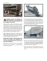
(Item 5) with lube and drive it home. Continue
lubing hub until lube emerges around seal’s
outside diameter.
PHOTO NO. 3011
GEARBOX
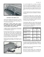
All widths 1000 RPM shredders are equipped with
a common 1.00:1.00 ratio gearbox. Refer to Photo
3008A and DWG. 6088 on page 38.
PHOTO NO. 3008A
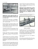
Gearbox can best be worked on as follows:
1. Detach tractor PTO at gearbox input spline.
2. Remove the left cross drive shaft shield. Loos-
en and remove left outboard drive shaft bear-
ing flange bolts. This can be done without re
-
moving the driveR sheave by slacking off the
backwrap idler and removing belts. This per-
mits sliding the entire left drive shaft assembly
leftward; thus, allowing room to slide the gear-
box loose from its R.H. spline coupling.
3. Remove the (2) right 3/8” bolts nearest the
gearbox holding the right cross shaft shield.
4. Remove the top 4 1/2” bolts holding the gear-
box/PTO input shield and remove this shield.
5. Remove the bottom 4 1/2” gearbox mounting
bolts and slide the gearbox leftward
sufficient
to uncouple it from its right splined coupler.
Then slide the gearbox forward to remove it
for placing on a workbench.
6. Remove the gearbox drain plug and discard
the lube.
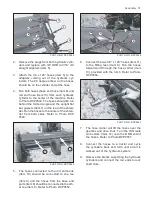
The gearbox has no shims because preload and
backlash are factory set. To service this box pro-
ceed as follows:
1. Remove (12) 3/8” socket head bolts (Item 1)
holding the 2 halves together. Tap input shaft
(Item 2) with a soft hammer, while holding the
output shaft (Item 3) off the work table. Be
careful to not damage the case’s mating sur-
faces by prying them apart.
2. The input and output shafts and gears are pre-
cision fitted. Do not separate them by prying
on an individual set. Lift them apart together.
3. Remove old anaerobic sealant and complete
necessary maintenance. Whenever a gearbox
is opened, all 3 oil seals (Item 4) should be
replaced. Lube the seal’s inside diameters be-
fore reinstalling and insure their spring garters
are toward the gearbox’s inside.
4. Clean gearbox of all dirt and metal particles.
Inspect all removed parts for wear. Replace
any bearing showing signs of pitting, inability
to rotate freely and discoloration. Clean any
bearings to be reused and coat with gear lube.
Replace gears showing pitting, breaks or de-
formation. Replace input and through shafts
having spline wear or deformation.
5. Whenever shafts are disassembled, make
sure the same thickness snap ring (Item 5) are
used to maintain backlash and preload. There
is 1 external snap ring used. For reassembly,
capture bearings and seals in appropriate ma-
chined areas. Tap gently with a soft hammer to
seat, being careful to not damage seals.
6. After both shafts have been reseated, apply
anaerobic sealant (eg. Locktite 518 (red) or
Perma-Lok HH 190 (dark purple) or Permatex
silicone sealant 765-1344/1485) to housing


