


Service 41
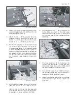
Insure both center cross shafts are correctly pi-
loting into needle bushings. See Photo 3043.
10. Seat needle bushings until both snap rings can
be reinserted. Before mounting other yoke, in-
sure center cross zerk is aligned for gun ac-
cess.
11. After completion of yokes and center cross as-
sembly, hammer strike all 4 yoke ears at (Item
4) for stress relief. Thoroughly lube joint as-
sembly before reinstalling shields and placing
on unit.
PHOTO NO. 3043
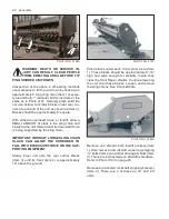
PTO-CONSTANT VELOCITY JOINTS
Following pertains to the “C.V.” (ie. not conventional)
joint used on tractor end of all trailing units. Service
procedures are similar to that previously covered un-
der conventional joints.
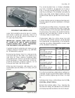
1.
Refer to Photo’s 3036, 3037, 3038 and 3039
page 39 for removal of necessary PTO shields.
2.
Relieve radial drag on the internal snap ring (eg.
(Item 1) in flange yoke (Item 2) by circumferen
-
tially tapping it with a drift. With snap ring pliers,
remove it. Repeat this for the opposite side of
the flange yoke. Refer to Photo 3044.
3.
With a good solvent, thoroughly remove all paint
around inner and outer surfaces of both needle
bushings. This is necessary to facilitate their re-
moval.
4.
Rest joint assembly in a vice with outer yoke
(Item 3) across top of vice jaws. Use CARE-
FUL hammer blows to drive center cross needle
bushing (Item 4) upward. Vertically rocking yoke
(Item 5), as bushing is driven out, provides ear
clearance between yokes (Item 2) and (Item 3).
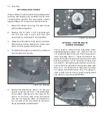
PHOTO NO. 3044
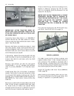
5. The partially extracted needle bushing (Item
1) can be removed with a Walterscheid tool
SW23 (Item 2). This tool inserts between vice
jaws (Item 3) and radially clamps the partially
extracted bushing.
6. Carefully rock flange assembly (Item 4) in di
-
rection of arrows (Item 5) until bushing is fully
out. Repeat this for other side of flange yoke
and separate it from center cross remaining in
undisturbed outer yoke (Item 6).
NOTICE: WALTERSCHEID TOOL SW23 IS NOT
SERVICED BY HINIKER. PROCURE DIRECT
FROM VENDOR At:
GKN Walterscheid Inc. 16 W 030 83rd ST.
2715 Davey Road
Woodridge, IL 60517
FAX (630) 972-9392 Ph (630) 972-9300
7. Repeat above steps to remove both needle
bushings and center cross from opposite end
(Item 7) of flange assembly. Refer to Photo
3041 and 3042, page 40 for removal of needle
bushings and center crosses from both outer
yokes. Rest their “bare” center crosses on the
vice jaws because they will be discarded.
IMPORTANT: NEVER POUND, OR OTHERWISE
ABUSE, ANY NEEDLE BUSHING’S REPLACE-
MENT INTERNAL SHAFTS.
8. Joint repair kits are serviced complete with cen-
ter cross, 4 needle bushings and 4 snap rings.
IMPORTANT: DIRT IS A PRIME ENEMY OF NEE-
DLE BEARINGS. INSURE YOKES ARE CLEAN
BEFORE REASSEMBLING NEW BEARINGS.
KEEP REPAIR KIT COMPONENTS THOROUGH-
LY CLEAN DURING INSTALLATION.


