Service 35
IMPORTANT: WHEEL SEAL AND RIDING
RING MUST BE INSTALLED IN THE RIGHT
DIRECTION, PROPERLY PRE LUBED AND
THE HUB FULLY PACKED WITH LUBE. IG-
NORING PROCEDURES BELOW WILL RE-
SULT IN PREMATURE CONTAMINATION AND
FAILURE.
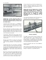
1. Remove hub, inboard bearing cone (Item
1), outboard bearing cone (Item 2) and seal
(Item 3) from spindle. Thoroughly clean
hub’s interior grease cavity, both bearing
cups (Item 4), cones (Item 1 and Item 2),
hub cap (Item 5) and pre load hardware.
2. Discard old seal (Item 3) and inspect bear-
ings for deterioration. Replace both cups
and cones if necessary. Generally, seal rid-
ing ring (Item 6) should be replaced when
doing wheel hub maintenance.
IMPORTANT: PRESS SEAL RIDING RING
INTO HUB WITH INTERIOR EDGE FLANGE
TOWARD INBOARD BEARING CUP. MANU-
ALLY WORK LUBE INWARD BETWEEN (3)
SEAL LABYRINTHS BEFORE INSTALLING.
CAREFULLY START NEW SEAL (ITEM 3)
ONTO SPINDLE WITH BEARING CONE (ITEM
1) WHICH CAN BE SEATED WITH A 3/16”
PUNCH OR 1 1/2” I.D. DRIVER. INSURE SEAL
IS NOT CROOKED AND IS INSTALLED WITH
ITS SHARP EDGED INSIDE FLANGE TO-
WARD THE OUTBOARD SPINDLE END. THE
OPPOSITE (SMOOTH) SEAL FACE IS USU-
ALLY MARKED “OUTSIDE”. THIS MUST AL-
WAYS FACE THE SPINDLE’S INBOARD END,
OTHERWISE THE SEAL WILL NOT FUNC-
TION CORRECTLY.
3. Install hub, outboard bearing cone (Item 2),
end washer and adjusting nut. Adjust nut
with a HAND WRENCH ONLY. Tighten un-
til seal is seated and bearings substantially
drag, then back nut off 1/6 turn to insert and
spread cotter.
4. Use zerk to fully lube hub cavity and bear-
ings, while rotating hub, and until lube emerg-
es through outboard bearing. Pack hub cap
9. Continue bolt torquing until above values oc-
cur, or NO LESS THAN 1/8” HUB FLANGE
TO SHEAVE CLEARANCE EXISTS. There
will always be a gap in the inner bushing
hub when proper procedure is followed.
NOTICE:
INDIVIDUAL
BOLT
TORQUES
SHOULD BE ACHIEVED NO MORE THAN 2
TIMES IN THE TIGHTENING CYCLE.
10. Reinstall belts and reposition backwrap
idler.
DRIVE SHAFTS BEARINGS
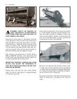
The front drive shafts bearings (Item 1) have ec-
centric lock collars (Item 2). To loosen these,
remove 3/8” Allen set screw therein. With a drift,
drive collar (Item 2) OPPOSITE to direction of
rotation of shaft (Item 3). When reinstalling
bearing, drive collar (Item 2) in SAME DIREC-
TION as rotation of shaft (Item 3) and retighten
set screw. See DWG. 2256A
Servicing these bearings requires removing the
driven sheave, See page 34-35 and extract the
drive shaft. Paint must be polished off drive shaft
to permit stripping it through the bearings.
1
2
3
1. Bearing 2. Bearing Collar 3. Shaft
DWG. NO. 2256A
WHEEL BEARINGS & SEALS
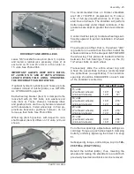
HINIKER shredders are equipped with O.D. rid-
ing triplex (3 labyrinths) seals. They also have
a replaceable seal riding ring (Item 6) and zerk
relube in the hub. This system is highly effective
when properly installed and maintained. See
Photo 3011 on page 36.


