14 Section
14 Field Preparation
After initial fielding, the wheel legs rockshaft
position is normally adjusted with the ratchet
jack(s) and left unchanged unless field condi
-
tions change.
SHREDDER-TRAILING HITCH
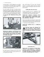
Trailing shredders have an adjustable hitch
height adjustment (Item 1) to match various trac-
tor drawbar heights. Refer to Photo 3555A.
IMPORTANT: CORRECT TRAILING HITCH
DRAFT LINK LENGTH ADJUSTMENT CAN-
NOT BE MADE UNTIL AFTER THE SHRED-
DER IS INITIALLY FIELDED.
Raise the shredder with hitch jack until the hitch
yoke corresponds with the tractor’s drawbar and
insert hitch pin. Always store the hitch jack (Item
1) as shown in Photo DCP0603.
IMPORTANT: ALWAYS USE A 1” DIAMETER
HITCH PIN.
CAUTION: DEATH OR SERIOUS IN-
JURY CAN RESULT. ALWAYS INSERT
THE HITCH PIN POINT DOWN WITH A
CROSS LOCKING PIN THROUGH ITS LOWER
END.
PHOTO NO. 3555A
SHREDDER-PTO’s
IMPORTANT: IT IS CRITICAL TO KNOW WHAT
TRACTOR CONFIGURATION IS INVOLVED
BEFORE HOOKUP. THE PROPER SHREDDER
PTO MUST BE USED, OTHERWISE UNSATIS-
FACTORY PERFORMANCE WILL RESULT.
Hitch jack (Item 1), Photo DCP0603 is not needed
on 3 point hitch units, except when an end trans-
port accessory is used. Its storage position is on
pedestal on top the gearcase.
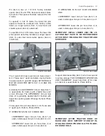
The “lost motion” slot (Item 1) provides ground
float when the tractor’s upper link (Item 2) is prop
-
erly length adjusted. Normally, cross pin (Item 3)
should operate in the REAR SECTOR of the slot.
That is, from the slot’s center position to about 1”
from its rear. Actual adjustment herein is made
by VARYING THE TRACTOR’S UPPER LINK
LENGTH.
1
PHOTO NO. DCP0603
IMPORTANT: CORRECT “LOST MOTION” AND
TRACTOR UPPER LINK ADJUSTMENT CAN
NOT BE MADE UNTIL AFTER THE SHRED-
DER IS INITIALLY FIELDED AND FINAL FIELD
SETTINGS ARE MADE.
PHOTO NO. 2972
No hose support is furnished with 3 point hitch
units because generally remote hydraulics are
not needed in this mode.


