


Service 33
11. Circumferentially polish rotor center stub
shaft and reinstall it in replaced bearing. In-
sure stub shaft shoulder is against bearing
inner race. Torque (2) Allen set screws once,
loosen and torque them a second time.
IMPORTANT: WHENEVER THESE LOCK NUTS/
BOLTS ARE DISCARDED, ONLY GRADE 5
BOLTS AND TYPE B LOCKNUTS SHOULD BE
REINSTALLED. THE ABOVE CITED (OR SIMI-
LAR) ANAEROBIC THREADLOCK SHOULD
BE USED IN REASSEMBLY OF BEARING
MOUNTING BOLTS AND ALLEN SET SCREWS.
TORQUE ALL BEARING MOUNTING BOLTS
TO 58-82 Ft/lbs. (79-112 N/m.).
12. Temporarily reinstall (4) 3/8” bolts through
outer bearing mounting plate and snug them
up. Do not reinstall outer anti-wrap shields at
this time. Check varying quantity of 2 3/16”
nominal I.D. washers between outer bear-
ing’s inner race and shoulder of rotor shaft.
If these are axially SNUG WITH NO PRE-
LOAD, proceed to completely reinstall outer
bearing and anti-wrap shields.
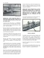
13. If washers are not as stated above, it will be
necessary to remove outer bearing. See Pho-
to DCP0659, page 31 and add, or subtract,
washers.
2 3/16” nominal I.D. washers are
available as part numbers:
Washer
Part Number
1/16” Thick
79202329
1/8” Thick
79202328
Check that all previously removed and/or
loosened parts are properly reinstalled. Re-
move hoist and reverse above tipping proce-
dure to return the unit to operating position
and reinstall previously removed hitch, etc.
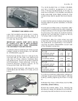
SHEAVES ALIGNMENT
It is unnecessary to realign sheaves unless they
have been damaged, removed or loosened. Do not
realign sheaves unless they are more than + or -
1/16” misaligned. See Photo DCP0618.
2
1
3
PHOTO NO. DCP0618
1. It is generally best to align driveR (Item 1) to
driveN sheave (Item 2); thus, only 1 sheave
need be loosened.
2. Determine misalignment by placing a steel
straight edge (Item 3) across sheaves as
shown. Move sheave in or out to align.


