


32 Service
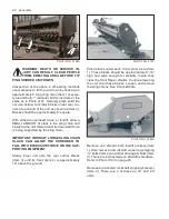
5. Securely block rear (Item 3) of each wheel
and approach shredder from REAR. Use a
chain sling (Item 4) approximately 5’ long
on each run. Fix EACH sling chain hook
SECURELY around both 1” diameter hitch
pins (Item 2) where shown by decal (Item 5).
Lift unit until wheels are about to clear the
ground.
PHOTO NO. 2990A
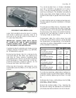
6. Move wheel blocks previously installed to op-
posite side of wheels (Item 1). LOCK RATCH-
ET JACK HANDLE(S) (Item 2) into position
shown to prevent damaging them. Swing unit
rearward and overcenter, then slowly lower
the unit to the ground. Open end shield (Item
3) and detach bottom enclosure plate (Item
4).
PHOTO NO. 3014
7. Loosen outer bearing from its mounting as
shown in Photo DCP0659 on page 31. Un-
less this bearing is also being serviced, it is
not necessary to remove it from the rotor at
this time.
8. Remove center anti-wrap shields. This allows
access, through the rotor’s inner end notches
to bearing’s inner race Allen set screws. De-
tach shield and lube tube.
9. Loosen (2) 3/8” Allen set screws (Item 1) from
center bearing (Item 2). These are retained
with anaerobic threadlock (eg. Locktite 242
(blue) or Perma-lok HM 118 (red). See Photo
DCP0591.
2
1
PHOTO NO. DCP0591
Commercial anaerobic threadlocks have instal-
lation instructions, and SAFETY CAUTIONS, on
their containers. These should be adhered to.
10. Attach chain sling around rotor. Outer end
of rotor is lifted above frame to obtain clear-
ance.
Axially pry rotor free of its inner bearing and
swing it clear of working area.
NOTE:
Care-
fully lift both split rotors together on units with
four rotors. Sling should be from center of ro-
tors to reduce stress on coupling.
DWG. NO. 6384


