


34 Service
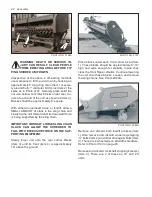
SHEAVES REMOVAL/INSTALLATION
1. Loosen belt’s backwrap idler and remove
belts.
1
2
3
5
6
4
PHOTO NO. DSCN4648B
2. Loosen and remove bolts from 3 UN-
THREADED holes (Item 2).
3. Insert these bolts in the 3 THREADED holes
(Item 3). Start with the bolt furthest from the
inner bushing’s slot (Item 4) and gradually
alternately torque bolts in a uniform pattern.
Continue torquing in small increments until
the tapered surfaces disengage. The same
procedure is used if driveN sheave (Item 6)
is to be removed.
NOTICE: EXCESSIVE AND/OR UNEQUAL
BOLT TORQUES CAN BREAK THE INNER
BUSHING’S FLANGE.
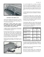
4. The inner bushings are retained with 3/8”
Allen set screws (Item 1) over their keyways
(Item 2). Remove the set screw to enable
removal of the inner bushing.
2
1
PHOTO NO. DCP0656
5. For installation, insure the tapered mating
surfaces of the inner bushing (Item 1) and
sheave (Item 5) are free of dirt, paint, rust,
metal chips and LUBRICANT.
IMPORTANT: DO NOT USE LUBRICANTS,
ANTISEIZE, AND/OR EXCESSIVE BOLT
TORQUES
WHEN
ASSEMBLING
Q.D.
SHEAVES. THESE CAN BREAK THE ASSEM-
BLY.
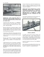
6. Insure woodruff key is in place before slid-
ing inner bushing on shaft. Align (in/out) the
Allen set screw hole of the bushing being
installed with existing witness marks on its
shaft and torque the set screw.
7. Align 3 UNTHREADED bolt holes with
THREADED bolt holes in mating sheave
or bushing. Inset bolts and lockwashers
in these UNTHREADED holes and tighten
about 2 turns each.
8. Alternately torque these bolts , in a uniform
pattern, until the tapers are seated (approxi-
mately 1/2 bolt torque). Check for sheave
alignment and possible wobble. Correct if
necessary.
IMPORTANT: SHEAVE BOLTS ARE ONLY
TORQUED TO VALUES:
Dia.
Ft/lbs.
N/m.
3/8”
30
24-33
1/2”
60
50-58


