


46 Assembly
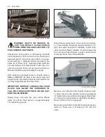
IMPORTANT: AFTER TRACTOR HOOKUP, AL-
WAYS STORE HITCH JACK ON PEDESTAL AT
TOP OF GEARCASE. (Item 1), Photo DCP0603.
1
PHOTO NO. DCP0603
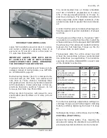
PTO’s
It is easiest to install the trailing PTO AFTER
completing the trailing hitch installation. It is
easiest to install the 3 point PTO BEFORE com-
pleting the 3 point hitch installation. Both PTO’s
are installed the same; however, Photo 2992,
page 48 shows only a 3 point PTO. See Page
18, Photo 3550 for Trailing CV PTO.
FOUR DIFFERENT PTO’s are available and are
variably shipped pursuant to dealer’s order:
1 3/8” (1000) 21 spline trailing all widths.
(55” Telescoped O.A. length)
Whole goods item 79202278
1 3/4” (1000) 20 spline trailing all widths.
(55” Telescoped O.A. length)
Whole goods item 79202277
1 3/8” (1000) 21 spline 3 point all widths.
(38 1/16” Telescoped O.A. length)
Whole goods item 520-02157
1 3/4” (1000) 20 spline 3 point all widths.
(39 1/4” Telescoped O.A. length)
Whole goods item 520-02159
All TRAILING PTO’s are C.V. (constant velocity)
and identified by extended front yokes separat-
ed by a large guide hub between them.
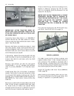
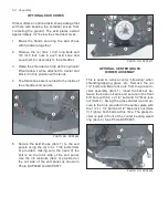
TRAILING HITCH
The trailing hitch bundle consists of the hitch “A”
frame (Item 1) and a lower adjustable draft link
(Item 2).
Remove both base unit draft pins (Item 3) and
position hitch (Item 1) with thicker hitch clip on
top (Item 4). Insert hitch’s rear brackets (Item 5)
between both sets of base unit ears (Item 6) and
reinstall pins (Item 3). Insure cotters on each end
of both pins are spread. See Photo 3555 below.
PHOTO NO. 3555
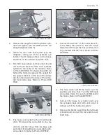
Remove rear draft pin (Item 2). Clip dunnage
at rear of the adjustable draft link (Item 3) and
install its rear bracket between base unit ears
(Item 4) with pin (Item 2). Insure both pin cotters
are spread. Remove the hose carrier and put it
aside.
PHOTO NO. 3556
Adjustable draft link is preset to facilitate an ap-
proximate 18 inch draw bar height and yield an
acceptable stubble. However, final adjustment to
a customers tractor drawbar height, must await
actual field operation.


