background image

40 


11.6  VFO Management 

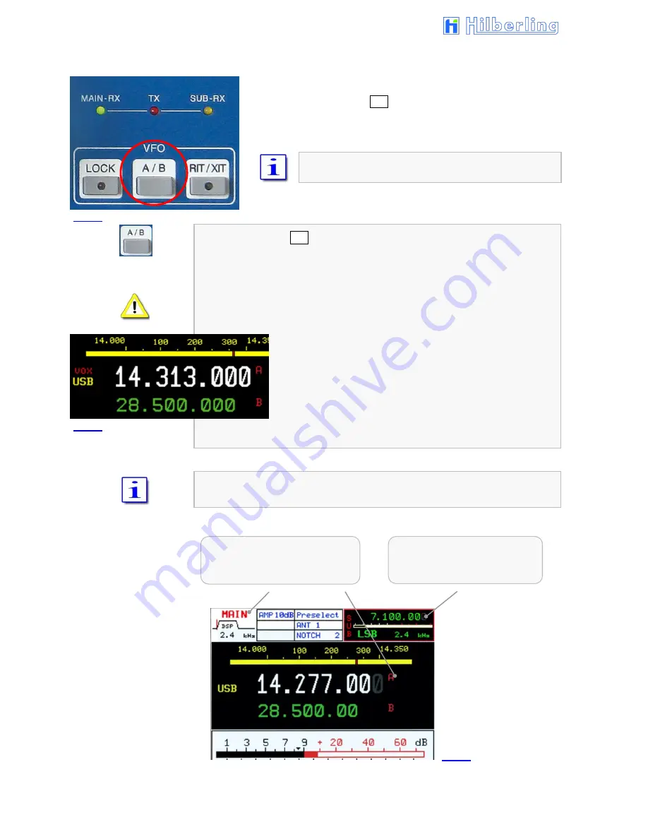
Both receivers (MAIN- and SUB-RX) have its own two VFOs – 

VFO A and VFO B. Switching between VFO A and VFO B is 

established through VFO A/B pushbutton. The button is located in 

the cluster VFO. 


In addition to frequencies the VFOs store filter 

bandwidth and operation mode. 


When pushing VFO A/B: 


In case the VFO softkey menu is already displayed the 

active

 RX will 

change its VFO (A

B or B

A). 


If a different softkey menu is displayed the first push will call up the VFO 

menu. The second push will alter the VFO A and VFO B. 


Both frequencies displayed for the 

active

 RX will alter its 

position. The white display always shows the 

selected


VFO. The VFO can be identified through the red 

nominators A respectively B. 


The smaller green display always shows the alternate VFO 

that is in 

standby

 mode. 


Only the SUB-RXs 

selected

 VFO frequency is displayed without its identifier A or 

B. 


active

 RX


(shown: MAIN-RX) 

selected

 VFO (shown: A) 

RX 

in the background 


(shown: SUB-RX) 

selected

 VFO (A or B) 

Fig. 49 

Fig. 51 

Fig. 50 

Summary of Contents for PT-8000A

Page 1: ...HF VHF Transceiver PT 8000A Operating Manual Version 2 00 33...

Page 2: ...Copyright notice to the ring binder title All Figure rights reserved by Bundeswehr PIZ Marine DGzRS and Hilberling GmbH...

Page 3: ...veloped and manufactured in the EU by Hilberling GmbH Kieler Strasse 53 24768 Rendsburg Germany Logo and name of Hilberling GmbH are registered trademarks Distribution of the complete Document is desi...

Page 4: ...R allow children or any unauthorized persons to operate the transceiver AVOID placing and using the transceiver in areas with temperatures below 15 C or above 50 C If the environment temperature drops...

Page 5: ...7 1 Introduction 11 7 2 Cable Connectors 11 7 3 Initial Settings 11 8 Operating and Display Elements 8 1 Main Operating and Display Elements 12 8 2 TFT Display 13 8 3 Clustered Front Panel Controls 1...

Page 6: ...udio NORM SPLIT 53 17 2 Calibration of Internal Reference REFERENCE CALIBRATION 54 17 3 Brightness of Display DIM 55 17 4 NF Recording VOICE RECORDER 56 18 Scale Select METER 57 19 Basic Settings RX T...

Page 7: ...ate and Update Software Windows Program A2 1 Preliminary Note A2 1 A2 2 Introduction A2 1 A2 3 Requirements and Procedure A2 1 A2 4 Setup Software and Firmware A2 2 A2 5 Install Update Program on PC A...

Page 8: ...erence in a residential installation FCC ID V84PT8000 This device complies with Part 15 of the FCC rules Operation is subject to the following two conditions 1 this device may not cause harmful interf...

Page 9: ...le HN 8000 PT 8000A 9 1 Ground Cable HN 8000 PT 8000A 10 1 Speaker Cable HN 8000 PT 8000A 11 1 Data Cable PC Notebook PT 8000A 12 1 Phono Plug 6 3mm 1 DB 25 Male Plug DSUB 25 pol 1 DA 15 Male Plug DSU...

Page 10: ...le any time Select a power outlet that is capable to handle the power requirements Connect your PT 8000A to a proper ground system which is important for optimum operation of any HF transceiver especi...

Page 11: ...mplifiers so they always see a SWR close to 1 0 The ATU has its limits tuning mismatches with SWR greater than 2 0 become difficult and will exceed the capabilities of the ATU Using a tuned or resonan...

Page 12: ...n preselector is disengaged J6 HF RX ANT SUB OUT SMA HF Antenna Signal for SUB RX after passing internal antenna switch respectively TX RX relay Connected to J7 by default or to input of external equi...

Page 13: ...s PC Hilberling software PT 8000A IF Monitor connecting cable J16 ext SPKR alt EIA 453 IEC 60603 11 TRS 3 5 mm Socket Output audio MAIN and SUB RX only SUB RX Audio Norm Split 4 5 W max 8 connection e...

Page 14: ...C IN 2 13 8 V DC RX switched by relay 1 50 V DC PA switched by relay 1 GND 2 13 8 V DC Relay HN switched to GND by PT8000 switch POWER J19 Keyboard 1 DATA 2 not connected 3 GND 4 VCC 5 CLK 6 not conne...

Page 15: ...No Name Figure Function And Outline 1 MIC PTT 0 dBm 1 MIC AUDIO IN 2 PTT 3 MAIN RX AUDIO OUT e g headset 4 0 dBm IN 5 MIC AUDIO IN DC 10 V internal 6 SUB RX AUDIO e g headset 7 MIC GND 8 PTT GND 2 PHO...

Page 16: ...ment 5 2 Connectors at Rear Panel Connection Sockets J1 J4 No Name Type Description J1 AC IEC 60320 C13 male connector Input main power 90 260 V AC 50 60 Hz cable P 10 Fig 8 J2 AUX 13 8 VDC 2x Socket...

Page 17: ...if desired an extra punch to the signal It is equipped with a microphone preamp Impedance is 600 1 kHz The acoustic characteristic is kidney shaped Finish Black anodized 6 2 Wiring Cables AC line volt...

Page 18: ...HN 8000 PT 8000A length approx 1 0 m Speaker cable HN 8000 PT 8000A length approx 0 9 m Data cable PT 8000A USB B PC USB A length approx 1 8 m 6 3 Operating Manual and Software Documention CD This ma...

Page 19: ...s is are connected properly Grounding stud is connected to station ground Grounding wire is connected to both PT 8000A and HN 8000 DC cable is connected to both PT 8000A and HN 8000 For initial opera...

Page 20: ...f HN 8000 ON and OFF s P 53 TFT Display The display represents the primary means to control through soft switches Softkeys and to show all relevant data for RX and TX operations Primary VFO Tuning Kno...

Page 21: ...n call up of superior or submenu Thus adapted softkey menus for almost all pushbuttons on the front panel allow direct access to many allocated functions RX in the background limited access through co...

Page 22: ...ON OFF Notch 1 47 Notch Filter IF IF Notch Filter ON OFF Notch 2 both ON Notch 1 2 7 12V Power Supply VHF For external purpose ON OFF AMP DC 60 Tab 10 No Module Function Description Options Page 1 VO...

Page 23: ...rated Transmit DISPLAY MENU Software Update Calibration Brightness Display Voice Recorder METER ALC COMP TX S Meter Scales DSP Activation of Digital FILTER 2nd IF Automatic Multi NOTCH Filter Automati...

Page 24: ...N FM Mode 1750 Hz Adjust Level MIC GAIN Adjustment Level VOX Activate OFF ON MIC PROCESSOR Speech Processor Activate OFF ON Adjust Compression Ratio 0 20 dB TX POWER PA Power Switch10W 200W Adjust Pow...

Page 25: ...ustment of sensitivity from MIC and Data Input are twofold Coarse adjustment P2 is Done at an early stage right after the input transformers MIC gain settings from the front panel controls amplifier a...

Page 26: ...ghtness of Display Recording Functions Voice Recorder Audio NORMAL SPLIT Setting 53 54 55 56 53 METER Scale selection ALC COMP S Meter dBm dB V 57 Tab 11c LED glows Meaning Page FILTER DSP Filter acti...

Page 27: ...tter and two receivers are operated in three main modes MAIN RX is active and SUB is working in the background green MAIN RX LED is on SUB RX is active and MAIN is working in the background yellow SUB...

Page 28: ...e volume of MAIN and SUB RX is permanently adjustable through the respective controls MAIN und SUB Both knobs have a push function Pushing MAIN will turn off PT 8000A speaker pushing SUB will turn off...

Page 29: ...hreshold to a new setting The large S meter is always allocated to the active RX The smaller S meter is indicating the field strength of the RX working in the background Transmitting TX is only possib...

Page 30: ...0 1 Single Side Band and Continuous Wave SSB CW Pushing SSB CW button activates the allocated last used mode USB LSB CW or CW and will call up the SSB CW menu If this is e g a SSB mode a second press...

Page 31: ...ch of the received signal is changing Tuning range 400 1000 Hz Increments 50 Hz DSP on and off Width Select filter bandwidth to following values DSP on 50 100 200 400 500 Hz DSP off 500 Hz fixed 250 H...

Page 32: ...AME left of frequency Cyclic change of frequency tuning steps 1 Hz 10 Hz 100 Hz 1 kHz Frequency Modulation standard mode the softkey will be displayed inverse as shown here the display will show FM le...

Page 33: ...this setting It can be modified by STEP VFO softkey in the same menu Alternatively use STEP VFO knob to set the frequency shift Pushing SET RPT again will terminate the SET RPT mode The frequency shi...

Page 34: ...ll be displayed inverse as shown here DATA LED will turn on the signal at the AUDIO DATA IN input J20 Pin 2 3 10 will be transmitted when PTT is switched In case this softkey is activated the softkey...

Page 35: ...usly when tuning within the band with VFO knob or STEP VFO knob In case the BAND limits are exceeded trough tuning the last valid frequency that has been stored will remain Press button again for retu...

Page 36: ...ncy used in VHF 50 MHz 70 MHz 144 MHz or 110 MHz The respective band will be displayed inverse in the VFO softkey menu s P 41 Like on HF the last two frequencies used on VHF are recalled through the 0...

Page 37: ...between the last two frequencies used within this band Select 6 m band the softkey will be displayed inverse pressing this key again will toggle between the last two frequencies used within this band...

Page 38: ...below VFO menu will be called up see Page 41 If transverter 1 is selected displayed inverse pushing again Trans 1 softkey will call up the Transverter Band Select menu applies accordingly Trans 2 Retu...

Page 39: ...3 1 268 1 270 GHz 4 1 296 1 298 GHz 5 2 320 2 322 GHz 6 3 400 3 402 GHz 7 3 456 3 458 GHz 8 5 760 5 762 GHz 9 10 368 10 370 GHz 10 10 450 10 452 GHz 11 24 048 24 050 GHz 12 47 088 47 090 GHz 13 75 97...

Page 40: ...AND buttons located in the cluster BAND and 0 VHF located in the cluster MODE will insert the digits from left to right Pushing ENTER button located in the cluster MODE or softkey again will complete...

Page 41: ...O Pushing ENTER is not required The RX operates with the new frequency In case the input is not acknowledged through ENTER or completely input or not aborted through ESC after a period of 10 seconds w...

Page 42: ...NEL menu will be called up see below The frequency display of the standby VFO will be substituted by information about the active channel see Page 35 Figure 42 When CHANNEL function is active toggling...

Page 43: ...marked by an asterisk If the frequency of the marked channel lies within the SCAN boundaries it will be used for SCAN operations If there was no memory content written to the VFO by pushing softkey C...

Page 44: ...e substituted by information about the selected memory channel see Page 37 Figure 45 When MEM function is activated toggling between MAIN and SUB RX is inhibited same with toggling VFO A and B Select...

Page 45: ...EM overwritten When overwriting a memory channel there is no warning Memory channels are accessible from both MAIN and SUB RX If the MEM menu is displayed pushing MEM will terminate this modus and the...

Page 46: ...13 and 14 In case the transmit boundaries are to be modified commercial application signal generator operation new amateur radio frequencies please contact Hilberling GmbH for further information abou...

Page 47: ...knob will now tune the VFO by 100 kHz steps Pushing the knob a second time will move the cursor to the 10 kHz digit Turning the knob will result in tuning the VFO by 10 kHz steps Pushing the knob a th...

Page 48: ...A If a different softkey menu is displayed the first push will call up the VFO menu The second push will alter the VFO A and VFO B Both frequencies displayed for the active RX will alter its position...

Page 49: ...Additional digits appear at the VFO frequency readout Softkey STEP towards coarse tuning increases the tuning increments by power of 10 Lesser digits appear at the VFO frequency readout SPLIT operatio...

Page 50: ...nsmitting even though there is selected a different mode in the SUB RX Only the frequency of the SUB RX will be used Procedure Tune with the active VFO from the MAIN RX to the desired receive frequenc...

Page 51: ...be activated power on default CLAR knob will be activated functions see below Fig 56 RIT or XIT and the offset frequency will be displayed right next to the frequency after power on RIT will be activ...

Page 52: ...nu will be called up If the RIT XIT softkey menu is not displayed pushing RIT XIT will call it up and a second push will terminate RIT XIT operation VFO menu will be called up RIT XIT LED will turn of...

Page 53: ...Shift the placement of the filters SHIFT function respective band pass tuning Activating DSP filtering is accomplished by the pushbutton FILTER located in the cluster DSP Bandwidth and Shift Pitch see...

Page 54: ...following bandwidths Xtal filters and analogue filters and passband shifts are available using WIDTH and SHIFT control when DSP is activated Width 1 0 1 2 1 4 1 6 1 8 1 9 2 0 2 1 2 2 2 3 2 4 2 5 2 6 2...

Page 55: ...tering is active and modes are changed to AM FM both NOTCHs will cease operation After power on both NOTCH filters are off 13 1 1 IF NOTCH Filter The IF NOTCH will be activated by pushing the control...

Page 56: ...NR is off after power on 13 3 Noise Blanker NB The RX NB will be activated by pushing the control RX NB which is located as depicted On the display it is outlined as NB Turning the RX NB control will...

Page 57: ...activated and the threshold has engaged i e the RX is silent push and hold the SQL to override the threshold momentarily For permanently deactivating squelch function set knob SQL fully counter clockw...

Page 58: ...l be displayed inverse Select AGC hang time 100 ms the softkey will be displayed inverse CW Mode only Toggles between RF AGC default value und Audio AGC see annotation below When pushing AGC the LED w...

Page 59: ...g the S Meter active RX The AGC threshold can be raised to a certain level where signals below are significantly less audible than signals above the threshold where AGC action will level out the audio...

Page 60: ...a time defined After this time has elapsed the scanning will continue If the squelch engages during the pause scanning will continue immediately When pushing SCAN SCAN LED will be on the frequency of...

Page 61: ...Access to Setting brightness of display DIM menu see Page 55 Access to recording functions VOICE REC menu see Page 56 RX speaker allocation the key toggles between Audio Norm Split see below 17 1 RX S...

Page 62: ...isplayed instead of the standby VFO frequency see Page 55 Figure 80a Pushing Ref CAL softkey CAL menu will call up Reference Calibration menu a dialog box is displayed instead of the standby VFO frequ...

Page 63: ...by turning the SUB VFO REF SET knob Tuning range 10 Hz Ref 1 ppm Pushing Ref Enter will terminate the input procedure the new value will be stored permanently 17 3 Brightness of Display DIM Pushing DI...

Page 64: ...e number and a yellow marker above the track graphic select track by turning STEP VFO knob Recording position and status is shown as R seconds and a blue bar in the graphic Play position is shown as P...

Page 65: ...b c Hams radio units S dB Input power 50 Ohm dBm Input voltage 50 Ohm dB V When pushing METER METER LED will be on METER menu will be called up Control voltage of the ALC will be displayed SSB mode on...

Page 66: ...TX and an additional RX antenna the display will show ANT 1 or ANT 1 RX if appropriate see Page 14 Table 10 No 4 the softkey will display as well inverse as shown Select antenna 2 the display will sho...

Page 67: ...IF 2 filter default filter for AM and FM mode as well as for SSB if filter bandwidth 2 9 kHz the softkey will be displayed inverse Select 3 0 kHz IF 2 filter default filter for SSB mode if filter ban...

Page 68: ...VHF see Page 14 Table 10 No 1 the softkey will be displayed inverse Access to IF 2 Filter menu VHF to select a different IF 2 filter see next Page When activating this function 12 Volt DC are fed to...

Page 69: ...ter bandwidth 2 9 kHz the softkey will be displayed inverse Select 3 0 kHz IF 2 filter default filter for SSB mode if filter bandwidth 2 9 kHz the softkey will be displayed inverse as shown here Selec...

Page 70: ...which offers following functions Access to 3 band equalizer for TX see next Page Activating TX Audio Leveler on off the display shows LEV above S Meter the softkey will be displayed inverse Access to...

Page 71: ...and in 1dB Steps Maximum gain is 9dB Select EQ band in a cyclic manner see Table 17 below Band 1 Band 2 Band 3 Decrease gain of selected EQ band in 1dB Steps Maximum gain is 9dB Reset all previous set...

Page 72: ...oftkey will be displayed inverse shown Select normal mode of internal keyer the softkey will be displayed inverse Reverses paddle function to accommodate left right hand operation on off the softkey w...

Page 73: ...g the knob selecting mode will be terminated Select TX passband shifting The Softkey will be displayed inverse for 4 seconds along the way turn STEP VFO knob to select new value after a period of 4 se...

Page 74: ...50 ms with 5 ms steps pushing Delay the softkey will be displayed inverse and turn STEP VFO knob input modus deactivated after 5 seconds inactivity TX EXT only Activation Wait for External Device The...

Page 75: ...activate the antenna tuner TUNER LED will be on 20 1 2 Start Re Tuning Cycle START Pushing START button will start the detection and storage for optimal adjustment of the antenna tuner at the current...

Page 76: ...ilberling T9 and in normal mode of speaking the knob should be adjusted between position clock 9 and clock 12 The correct modulation can be monitored on the ALC display see Page 57 SSB mode only If th...

Page 77: ...se an external one choose TX EXT in the TX OUT menu Page 66 the scale below is always shown TX EXT Power 100 mW 20 6 VOX Operation Pushing the knob MIC will activate VOX Voice Operated TX operation Vo...

Page 78: ...voiding acoustic feedback Setting control fully counter clockwise for terminate MONITOR function 20 8 Fall Time TX for CW TX DELAY Turning TX DELAY will impact the time for transmit receive switching...

Page 79: ...Appendix A1 IF Monitor Software Windows Program A2 Firmware Update and Update Software Windows Program A3 Technical Documents A4 Customer Information A5 Lists...

Page 80: ...Blank Page...

Page 81: ...solution All in all is required 1 Windows computer featuring Windows XP Vista 7 administrator rights required 3 MB free disk space memory Audio input internal or external sound card with a 192 kHz sam...

Page 82: ...he Windows desktop A1 5 Connect PT 8000A to PC by Audio Cable For transmission of the audio data connect audio input of the PC Line IN 3 5 mm stereo phone jack to the PT 8000A socket J15 ext SPKR add...

Page 83: ...the frequency range below A1 6 2 Automarker and Marker The Automarker light blue circular ring indicates the strongest signal within the current panorama width for each MAIN and SUB RX The strength o...

Page 84: ...activated each time the program was started and can be activated by clicking Peak hold Fig A1 6b A1 6 4 Sample Rate and Buffer Setup When the program is new installed it is recommended to check the se...

Page 85: ...r connected according to A1 5 page A1 2 3 The PC is prepared for audio signal recording 192 kHz If note 1 and 2 are ok but the PT 8000A receiving signal cannot be seen in the panorama display check no...

Page 86: ...be seen on IF Monitor If not all controls are shown which should be verified open the menu Options and click Properties The window Properties will be opened Fig A1 14 Make sure that the boxes of Recor...

Page 87: ...Automarkers displayed Peak value is equal to value shown on the PT 8000A display Range 20 dBm in 1 dBm steps default value is 0 3 If the curve exceeds the display range both dBm scale and curve jointl...

Page 88: ...Default width is 140 dBm respectively 10 150 dBm In case other ranges of scale are displayed as shown in the right column then at least one of the two values for Scale move and Move screen in the dial...

Page 89: ...her RX will be omitted To view the waterfall chart of MAIN RX open the menu Tools and click the entry Waterfall Main The waterfall chart will be displayed instead of the panorama display of SUB RX in...

Page 90: ...erfall Now both panorama displays of MAIN and SUB RX will be displayed in the areas II and III of the program window To adjust the panorama display to make out useful signals and noise by different co...

Page 91: ...unning the operating system Microsoft Windows A2 3 Requirements and Procedure To update the PT 8000A operation programs firmware are required 1 Windows computer featuring Windows XP Vista 7 Administra...

Page 92: ...unpacked before further use A2 5 Install Update Program on PC To start the installation double click the file setup_PT8000_Update exe On CD ROM it can be found in the directory Software If the file w...

Page 93: ...fter clicking OK in the error message box Fig A2 3 the Set COM port window Fig A2 4 will be opened to select a different COM port in the background the main program window already will be displayed It...

Page 94: ...to navigate to the directory where you have stored the new operation program s firmware received from Hilberling GmbH e g C Downloads Select from the dialog box Open the new operation program in this...

Page 95: ...he file names give clues to the CPU as well as the version number CPU File Name Version MAIN CPU PT8_MAIN_0100 H86 M 01 00 RX CPU PT8_RX_0121 H86 R 01 21 ANT Tuner CPU PT8_ANT T_0110 H86 K 01 10 A2 8...

Page 96: ...the main display area An update of the DISPLAY software is currently not required Select from the Software menu Figure A2 16 the one CPU of which new operation program you have selected in Chapter A2...

Page 97: ...and PC are connected via USB cable A2 6 2 The update program has been started a COM port is connected and the new operation program update file is loaded A2 7 3 The PT 8000A is ready to update A2 8 4...

Page 98: ...ower area On the PC a message box prompts you to start the program transfer Click OK to start the program transfer In case the new operation program has the same version number as the current version...

Page 99: ...PT 8000A will show the total number of bytes to be transferred and the state of the bytes current transferred In the PC update program the field Bytes sent and the blue progress bar also will show th...

Page 100: ...process for the RX CPU is displayed The ANT Tuner CPU is updated in the same manner Pushing RX Update softkey SOFTWARE menu Fig A2 16 17 will start the update process for the RX CPU The Display will...

Page 101: ...program update file is loaded A2 7 3 The PT 8000A is ready to update A2 8 4 The Update standby mode of the PT 8000A and the loaded operating program agree respecting the CPU MAIN CPU Click the Start...

Page 102: ...display will show these numbers in lower area Pushing ESC leads back to the screen and the softkey menu Softwareversion Fig A2 16 17 Prompt see Fig A2 35 Display of current and new program version On...

Page 103: ...version Fig A2 16 17 Warning notice The new program version number is lower than the current one Prompt to confirm the program transfer on the PC Display of current and new program version On the PC a...

Page 104: ...to be transferred Prog Bytes Bytes Sent amount of data transferred by now The program transfer may take up to 30 minutes depending on the size of the operation program When data transfer is completed...

Page 105: ...age box Switch off the PT 8000A with the POWER switch and restart after a waiting time of about 10 seconds After restart the transceiver operates with the new transferred operation program Quit the up...

Page 106: ...A2 16 Blank Page...

Page 107: ...ic Range TX All Mode Frequency Range 1 8 30 MHz 160 80 60 40 30 20 17 15 12 10 m Band 50 54 MHz 69 9 70 5 MHz 144 148 MHz 6 4 2 m Band Mode AM AME SSB CW FM AM AME SSB CW FM Output Power 50 Watt 200 W...

Page 108: ...A3 2 Blank Page...

Page 109: ...trieb von Amateurfunkger ten Bereits der Erwerb und der Besitz dieses Ger tes durch nicht berechtigte Personen k nnen strafbar sein Der PT 8000A und alle eventuell nach und vorgeschalteten Zusatzger t...

Page 110: ...ung hin Entsprechend dem deutschen Gesetz ber das Inverkehrbringen die R cknahme und die umwelt vertr gliche Entsorgung von Elektro und Elektronikger ten kurz ElektroG ist die Hilberling GmbH bei der...

Page 111: ...t Panel Controls Overview 15 Compression TX Audio PROC 68 Compression TX Audio Level Meter COMP 57 Connectors at Front Panel 7 Connectors at Rear Panel 4 5 Control Knobs Front Panel Overview 16 CW SSB...

Page 112: ...s with LED Status Display 18 Recall of Stored Frequencies CHANNEL 34 Receiver Select MAIN SUB 20 Recording VOICE RECORDER 56 Reference Internal Calibration CAL 54 Repeater Mode FM 25 RF AGC Automatic...

Page 113: ...CORDER Audio Recording 53 56 Volume Adjustment Headphones Speaker 17 Volume Preadjustment 17 VOX Threshold 69 VOX Voice Operated TX 69 VOX ANTI TRIP Activating Suppression 70 VOX DELAY Hold Time 70 Wi...

Page 114: ...7a Status Field HF Mode 14 17b Status Field VHF Mode 14 18 Clustered Front Panel Controls 15 19a b Controls with Integrated Push Button Function Front Panel 16 20 Input Level Controls Left Hand Side 1...

Page 115: ...5 59a b FILTER WIDTH SHIFT Knob Display 45 60 IF NOTCH Knob IF Notch Filter 47 61 IF NOTCH Indicator in the Status Field 47 62 DSP NOTCH Button Digital Multi Notch Filter 47 63 DSP NOTCH Indicator in...

Page 116: ...tivate 67 99 START Button Antenna Tuner Start Re Tuning 67 100a c TX ON Button LED Status Display 67 101 ZERO BEAT Knob 68 102 MIC VOX Knob 68 103 PROC Knob 68 104a d TX POWER Knob Power Meter Scales...

Page 117: ...se A2 4 A2 9 Select new Operation Program Dialog Window A2 4 A2 10 Update File and Version Indicator A2 4 A2 11 Data Length Indicator A2 4 A2 12 Start Button active A2 5 A2 13 Update File Indicator No...

Page 118: ...2 38 RX CPU Operation Program does not match to CPU A2 12 A2 39 RX CPU Software Update Version Comparison A2 12 A2 40 RX CPU Start Program Transfer A2 12 A2 41 RX CPU Software Update Version Compariso...

Page 119: ...Panel 7 7 Connection Sockets J1 J4 Rear Panel HN 8000 8 8 Main Operating and Display Elements PT 8000A Front Panel 12 9 More Indications on the Display 14 10 Displayed Options in the Status Field 14 1...

Page 120: ...tch Filter Mehrfach Kerbfilter NB Noise Blanker St raustaster gegen impulsf rmige St rungen NR Noise Reduction Rauschunterdr ckung PTT Push To Talk Schaltung in den TX Betrieb RF Radio Frequency Hochf...

Page 121: ...PT 8000A Appendix A5 v2 00 33 A5 11 Intentional Blank Page...

Page 122: ......

Reviews: