


28
Henrad CC FF
- Installation
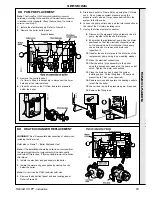
38 ELECTRICAL CONNECTIONS
Note.
Ensure that the lengths of
the current conductors are shorter
than the earth conductor so that if
the cable slips in its anchorage
the current carrying conductors
become taut before the earth
conductor.
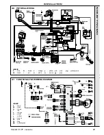
39 INTERNAL WIRING
Note.
If the timer kit is to be fitted refer to the instructions
provided with the kit, and Frame 40.
A pictorial wiring diagram is shown in Frame 40.
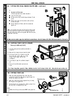
1. Ensure a length of 200mm between the wall and the connector.
Fix the cable(s) to the mounting frame with the clamp(s).
2. Wire the mains cable into the connector terminal strip (supplied
in the hardware pack).
3. Offer the connector to its mating half inside the boiler. Secure the
connector to the panel with the screw.
Incoming mains wiring detail
INST
ALLA
TION
INSTALLATION
WARNING.
This appliance MUST be efficiently earthed
A mains supply of 230 V ~ 50 Hz is required.
The fuse rating should be 3 A.
All external controls and wiring MUST be suitable for mains
voltage. Wiring should be 3 core PVC insulated flexible cord
NOT LESS than 0.75 mm
2
(24 x 0.2mm) and to BS. 6500,
Table 16.
(0.5mm
2
flex is NOT acceptable - for mechanical,
not electrical - reasons.)
Wiring external to the boiler MUST be in accordance with the
current I.E.E. (BS7671) Wiring Regulations and any local
regulations.
Connection must be made in a way that allows complete
isolation of the electrical supply - such as a double pole
switch, having a 3mm (1/8") contact separation in both poles,
or a plug and socket serving only the boiler and system
controls.
The means of isolation must be accessible to the user after
installation.
Summary of Contents for CC 100 FF
Page 1: ......