background image

Object directory

504

A4354-2.2


HBM: public

PMX

Please note that two 

files are created. The browser’s

download box appears two times.

The 

Structured Text 

(ST, SCL) file for PLCs is

importable in selected PLC configuration tools only. If not,
copy-and- paste the content in your source code.

The files contain a list of all data objects, types, and con­
stants definitions.

Important

Note that changing the hardware configuration and
adding, moving or deleting computed channels changes
the object directory. After that the OD files must be gene­
rated again.

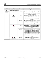
Summary of Contents for PX401

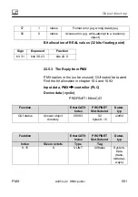
Page 1: ...Operating Manual English PMX...

Page 2: ...0 Fax 49 6151 803 9100 info hbm com www hbm com Mat 7 2002 4354 DVS A4354 2 2 HBM public 11 2016 E Hottinger Baldwin Messtechnik GmbH Subject to modifications All product descriptions are for general...

Page 3: ...X web server software 36 6 Degree of protection housing shielding design 41 7 Mounting Dismounting Replacing 43 7 1 Mounting tools and tightening torques 43 7 2 Support rail mounting 44 7 3 Wall mount...

Page 4: ...ource 20 mA 81 8 4 3 4 IEPE transducers with external measuring amplifier 82 8 4 3 5 PX401 with charge amplifier 83 8 4 4 PX460 87 8 4 4 1 Voltage supply for signal transmitter and transducer up to 24...

Page 5: ...dbus module 115 8 6 3 Pin assignment PX01PN PROFINET IO fieldbus module 116 8 7 TEDS transducer 116 8 7 1 TEDS connection 116 8 7 2 Starting up the TEDS module 118 8 7 3 PMX parameterization with TEDS...

Page 6: ...11 5 2 Factory settings 147 11 6 PMX startup behavior 148 11 7 PMX operating behavior 149 11 8 Signal runtimes 151 11 9 Fieldbus integration 156 11 9 1 PROFINET connection 156 11 9 2 EtherCAT connecti...

Page 7: ...2 7 Mean values arithmetic RMS 196 13 2 2 8 Moving Average 198 13 2 2 9 Trigger function range 199 13 2 2 10Trigger function pulse 201 13 2 3 Mathematical functions 204 13 2 3 1 Adder 204 13 2 3 2 Mu...

Page 8: ...orce displacement measurement with relative zero point 248 13 3 6 Checking force against a tolerance band 254 13 3 7 Event counter 261 14 Test signals and signal generators 265 15 Parameter sets measu...

Page 9: ...e WGX001 only 314 17 1 General 314 17 2 CAN pin assignment 314 17 3 CANopen master slave operation 316 18 CODESYS V3 Soft PLC WGX001 only 318 18 1 General 318 18 3 Preparation 321 18 4 Create project...

Page 10: ...ta acquisition software DAQ catmanEASY AP 395 21 PMX command set API 397 21 1 Requirements 397 21 1 1 Example TELNET connection 398 21 2 Command list 400 21 3 Examples 482 22 Object directory 487 22 1...

Page 11: ...tall firmware 508 24 Diagnosis and maintenance 510 24 1 Error messages Operating state LED display 510 24 2 Error messages of the device status 516 24 2 1 Error in factory settings 517 24 2 2 SYNC Mas...

Page 12: ...s for system status 528 24 8 2 System log entries for channel status measured value status 529 25 Quality certification and calibration certificates 531 26 FAQs 532 27 Technical support 537 28 Waste d...

Page 13: ...ing up the equipment you must first run a project planning and risk analysis that takes into account all the safety aspects of automation technology This particularly concerns personal and machine pro...

Page 14: ...ucted to carry out installation starting up maintenance or repair of the module must have read and understood the Operating Manual and in particular the technical safety instructions Conditions at the...

Page 15: ...nt planners installers and operators should plan implement and respond to the safety engineering considerations of measurement technology in such a way as to minimize remaining dangers On site regulat...

Page 16: ...age to property Safety instructions are structured as follows WARNING Type of danger Consequences of non compliance Averting the danger S Warning sign draws your attention to the danger S Signal word...

Page 17: ...to property Working safely Notice The device must not be directly connected to the DC voltage supply system Supply voltage 10 V 30 V DC The supply connection as well as the signal and sense leads must...

Page 18: ...BM The product is delivered from the factory with a fixed hardware and software configuration Changes can only be made within the possibilities documented in the operating manual Qualified personnel Q...

Page 19: ...ent in accordance with safety engineering standards It is also essential to comply with the legal and safety requirements for the application concerned during use The same applies to the use of access...

Page 20: ...Waste disposal and environmental protec tion page 539 CE mark The CE mark is used by the manufacturer to declare that the product complies with the requirements of the relevant EC directives the Decl...

Page 21: ...mplifiers pmx 3 1 Using this manual Read this operating manual thoroughly and in full before operating the device for the first time Look upon this operating manual as part of the product and keep it...

Page 22: ...printed summary of the safety instructions S The specifications data sheet in PDF format S A PDF version of the web server Online help The complete description of the functionalities and operation can...

Page 23: ...are explained below see Chapter 28 Waste disposal and environmental protection Symbol Significance List Cross reference to another point in this document or to other documents This prompts you to tak...

Page 24: ...e resolved with this measurement system Connection to a PC HOST The PMX measuring amplifier system is connected to a PC via the standard ETHERNET interface and can be parameterized and operated via th...

Page 25: ...easurement with strain gages SG and also has four channels with 24 bit resolution and TEDS sensor detection S The measurement card is suitable for strain gages in both half bridge and full bridge circ...

Page 26: ...transducers or pulse counters Or four measuring channels for frequency measurement up to 2 MHz incl two shunt calibrations and two 1 Wire TEDS sensor detection PX878 S The PX878 input output card has...

Page 27: ...ically detected This efficiently minimizes setup times and user error PMX web server An easy to operate web server that is specifically tailored to the PMX and is suitable for the measurement cards is...

Page 28: ...uments LabVIEW is a registered trademark of National Instruments Device implementation The multi client capability of the PMX makes it possible to access the device simultaneously and without loss of...

Page 29: ...2 3 10 6 12 Nr Bezeichnung 1 Communication card EtherCAT or PROFINET EtherNet IP 2 Fieldbus status LEDs 3 Measurement card status LED 4 RJ45 Ethernet socket to PC Network 5 USB Host 6 CANbus WGX001 on...

Page 30: ...s a modular and universally applicable measuring amplifier system The measurement cards input output cards and communication cards can be individually combined and intelligently configured in accordan...

Page 31: ...ensors piezoresistive sensors TEDS 0 wire PX460 Frequency counter measuring amplifier Up to four torque flanges T10 T12 T40 for torque or speed measurement without direction of rotation detection Or t...

Page 32: ...l inputs 8 digital outputs 5 analog voltage outputs all individually configurable Communication cards Module Interface Description PX01EC EtherCAT 1 module EtherCAT slave PX01PN PROFINET IO module PRO...

Page 33: ...Model overview scope of supply accessories PMX A4354 2 2 HBM public 33 Overview of measurement cards and input output card...

Page 34: ...unting 2 units packed in film cushion packaging with the mounting material in an Etimex bag 4 M5x10 close tolerance screws 4 spring washers 1 RAILCLIP PMX system CD with operating manual and data shee...

Page 35: ...plug and labeling sheets Set of screw terminal for PMX voltage supply 1 x 2 pin incl coding plug and labeling sheets Set of plug terminals push in for PMX plug in cards 2 x 13 pin and 2 x 2 pin incl c...

Page 36: ...rver including Help is integrated in the device The web server also has a firmware loader function which can transfer new PMX firmware and web server versions to the PMX An online Help is integrated i...

Page 37: ...o acquire condition and analyze the PMX measurement data as an option This allows vast quantities of measurement data to be displayed stripchart function and analyzed see following All real and calcul...

Page 38: ...surement signal and setting the filter frequency for each individual channel You can use the catman Script programming language to program complete measurement sequences including automated storage of...

Page 39: ...network Measurement configuration Set sample rate filter zero Sensor configuration Set scaling 2 point or via TEDS Analog In DAQ and calculated channels streaming Read all measuring values and time s...

Page 40: ...nds of the PMX command set can be used as low level commands see chapter 21 You can find extensive support and programming ex amples in the program help for the individual drivers All drivers and the...

Page 41: ...ternational Protection which are always present in the designation are followed by two digits These indicate which degree of protection a housing offers against contact or foreign bodies first digit a...

Page 42: ...of the cable shield means that the entire measuring chain is completely enclosed by a Faraday cage wh bk rd bu gn gy ye Fig 6 1 Greenline shielding design Important Use standard HBM cables for connect...

Page 43: ...Hexagon socket screwdriver 2 5 a f 1 0 1 2 Nm Mounting DIN rail on housing M5 hexagon socket screw Hexagon socket screwdriver 3 a f 3 Nm Mounting front panel M2 5 Torx screws Torx screwdriver TX8 0 5...

Page 44: ...a f Fig 7 1 Mounting on a support rail Undo the four back panel screws Torx T10 1 Slide the side parts forward 2 Screw on the support rail mounting Rail Clip 3 approx 5 Nm in a choice of four position...

Page 45: ...n height When using a smaller support rail 7 5 mm high it should be shimmed to make it easy to hook unhook the PMX device The 7 5 mm support rail can only be used in the top two positions A and B Atta...

Page 46: ...irradiation of external devices Faulty measurements due to electromagnetic irradiation from other devices To ensure adequate grounding for the PMX the support rail must be connected to a functional ea...

Page 47: ...mounting instructions 200 141 200 122 variable 141 min 25 133 5 Height of support rail 15 mm Height of support rail 7 5 mm Min dimension Plug plus sensor cable NOTE To ensure sufficient ventilation c...

Page 48: ...ing Dismounting Replacing 48 A4354 2 2 HBM public PMX 7 3 Wall mounting 1 225 215 152 4 3 168 5 Fig 7 2 Mounting on a wall Attach the wall bracket at the back of the PMX with the enclosed M4 screws 1...

Page 49: ...the complete unit to a wall hole 4 mm Notice Device damage caused by electromagnetic irradiation of external devices Faulty measurements due to electromagnetic irradiation from other devices The hous...

Page 50: ...below neighboring devices 7 4 Replacing measurement and communication cards Measurement and communication cards can be retrofitted or removed at a later date Please note the combination options see c...

Page 51: ...ore they are removed or replaced Always disconnect the PMX from the power supply before removing a card Note that the device settings have to be re parameterized if new cards are added The instruction...

Page 52: ...s prevent tilting 2 The board centers itself in the VG strip at the back 3 Re tighten the three M2 5 screws Notice Device damage caused by electromagnetic irradiation of external devices Faulty measur...

Page 53: ...ductors are to be connected to a terminal the line cross section must be adapted accordingly End sleeves without plastic collars 10mm should be used on the strands to connect the wires to the terminal...

Page 54: ...lug for PC network connection USB host e g for a memory stick CAN for CAN driver M12 option WGX001 4 Communication cards PX01EC EtherCAT PX01PN PROFINET IO PC01EP EtherNet IP or blanking plate 3 2 1 5...

Page 55: ...of plug ins Fieldbus or blanking plate x 0 1 PX401 x x x x 0 4 PX455 x x x x 0 4 PX460 x x x x 0 4 PX878 x x 0 2 8 2 2 Relevance of the basic device connection sockets PC or network connection Cable...

Page 56: ...apter 8 1 Supplying voltage to the PMX by connecting a separate DC voltage supply PMX basic device Cable Connector Female connector CAN connection type WGX001 only xx Pin Signal Description 1 SHLD CAN...

Page 57: ...LED LED Status Significance Ethernet Link 1 green Steady Connection is present Ethernet RX TX 2 yellow Flashing Data are being transmitted SYNC IN OUT 3 4 and 5 6 LED LED Status Significance IN 3 gre...

Page 58: ...54 2 2 HBM public PMX SYS LED 7 LED Status Significance green On Off Voltage supply available Voltage supply missing yellow On Device is booting red Flashing On Serious internal error or Firmware upda...

Page 59: ...No error red Flashing Configuration error red Single flash Synchronization error red Double flash Application timeout error red On PDI timeout error LED LED Status Significance RUN green Off INIT stat...

Page 60: ...Electrical connections PMX 60 A4354 2 2 HBM public PMX LED LED Status Significance 1 green Permanently on Flashing Off Connection established Send Receive No connection 2 No function...

Page 61: ...nection even to the message router the network status display will light up and remain green green Flashing No connections If the device has no existing connections but has received an IP address the...

Page 62: ...s no IP address or is switched off the network status display does not light up LED LED Status Significance MS green On Device operational If in operation and running correctly the network status disp...

Page 63: ...es green red when the device is carrying out a self test Off Not switched on If the device is not switched on the module status display does not light up LED LED Status Significance 1 green On Connect...

Page 64: ...em error incorrect configuration Flashing for device detection is controlled by the IO controller BF red On Flashing No connection or no configuration Bus error incorrect configuration not all IO devi...

Page 65: ...onnections PMX PMX A4354 2 2 HBM public 65 8 2 5 Measurement card LEDs PX401 channel status Status LED LED Status Significance green On no errors yellow Flashing Firmware update red On Parameter not O...

Page 66: ...HBM public PMX PX455 channel status Status LED LED Status Significance green On no errors yellow On Flashing No transducer connected or wire break self calibration ongoing Firmware update red On Param...

Page 67: ...X A4354 2 2 HBM public 67 PX460 channel status Status LED LED Status Significance green On no errors yellow On Flashing No transducer connected or wire break or firmware update red On Parameter not OK...

Page 68: ...LED per channel LED Status Significance Digital green On Off Digital output High Digital output Low green On Off Digital input High Digital input Low Analog green On Off Analog output configured Anal...

Page 69: ...e the enclosed safety instructions With a separate DC voltage power supply 10 to 30 V DC nom 24 V power output at least 20 W the PMX device is supplied with voltage via the POWER socket 1 see Chapter...

Page 70: ...n ATEX test certificate must be available for the transducers used Transducers with 350 ohm bridge resistance can be used One transducer per measurement channel of the PC455 can be operated parallel c...

Page 71: ...4 2 PX455 Four individually configurable 4 SG full or half bridges 4 8kHz CF Inductive full or half bridges LVDT potentiometric sensors piezoresistive sensors TEDS 0 wire sensor detection 0 wire TEDS...

Page 72: ...bles wh white bk black bu blue rd red ye yellow gn green gy gray Sense lead Cable shield wh bk bu gn gy Sense lead Sense lead Cable shield SG and inductive half bridges Measurement signal Measurement...

Page 73: ...ire configuration Cable color code wh white bk black bu blue rd red ye yellow gn green gy gray 1 2 3 4 3 2 wh bk rd bu ye Feedback bridges for a four wire configuration Four wire connection full bridg...

Page 74: ...es wh white bk black bu blue rd red ye yellow gn green gy gray LVDT transducer Sense lead Cable shield Measurement signal Bridge excitation voltage Bridge excitation voltage Sense lead Measurement sig...

Page 75: ...lead Fig 8 4 PX455 plug terminal potentiometric transducer Important Transducer connection in a four three wire configuration When connecting a transducer in a four three wire configuration the sense...

Page 76: ...aximum tolerance of 0 1 is added to a Pt100 resistor to make a half bridge circuit The PMX calculated channel Pt100 on PX455 converts the meas ured bridge unbalance to degrees Celsius and performs a c...

Page 77: ...A4354 2 2 HBM public 77 1 2 3 2 3 Cable shield Measurement signal Sense lead Sense lead Bridge excitation voltage Bridge excitation voltage PX455 Resistance thermometer Fig 8 5 PX455 with PT100 eleme...

Page 78: ...2 2 HBM public PMX 8 4 3 PX401 Four individually configurable current or voltage inputs with 4 TEDS 1 wire sensor detection 1 wire TEDS see Chapter 8 7 3 IEPE sensors can also be operated in combinati...

Page 79: ...connections PMX PMX A4354 2 2 HBM public 79 8 4 3 1 Voltage source 10 V U Cable shield U TEDS OUT OUT Excitation for external transducers 1 2 TEDS module optional Fig 8 6 PX401 plug terminal Voltage s...

Page 80: ...ons PMX 80 A4354 2 2 HBM public PMX 8 4 3 2 Current source 20 mA I I TEDS TEDS module optional OUT OUT Excitation for external transducers Cable shield 1 2 Fig 8 7 PX401 plug terminal Current source 2...

Page 81: ...4 3 3 Current source 20 mA I I TEDS TEDS module optional OUT OUT Cable shield 1 2 Sensor supply and measure ment signal are sent through a connection cable Sensor supply comes from the PX401 Fig 8 8...

Page 82: ...a voltage signal that can be controlled with the PX401 via an external module 8 4 3 4 IEPE transducers with external measuring amplifier Cable shield 1 2 3 1 wire EEPROM optional view from below 2 Da...

Page 83: ...onvert the sensor signal into a 10 V voltage signal The reset operate charge amplifier signal can take place in the PMX from an external controller or via a PX878 digital output The CMA charge amplifi...

Page 84: ...able shield 24 V gy pk rd wh PIN 5 6 4 8 1 CMA charge amplifier Piezoelectric sensor Charge cable 1 2 4 5 6 Signal Signal 7 0 V PX401 PX401 3 TEDS transducer identification 1 5 6 PX878 Terminal 2 digi...

Page 85: ...voltage is identical to the device supply voltage The maximum current is 400 mA per measurement card and is distributed across the used transducers Important The individual measurement channels on th...

Page 86: ...Electrical connections PMX 86 A4354 2 2 HBM public PMX All four channels at one potential Channel 4 Channel 1 Potential isolation PX401 housing WGX basic device Fig 8 11 Potential isolation PX401...

Page 87: ...ue flanges T10 T12 T40 for torque or speed measurement without direction of rotation detection Or two torque flanges for simultaneous torque and rotational speed measurement without direction of rotat...

Page 88: ...ltage with the contacts IN The PX460 card then provides the supply for 24 V OUT and 5 V 5 V OUT The input signals fed from the sensor into the PX460 must not exceed max 12 V Otherwise the measure ment...

Page 89: ...Nominal rated voltage 24 VDC looped through protected 2 A max max 12 V max 12 V max 12 V Sensor supply Sensor input signals Feed sensor supply NOTE The input signals fed from the sensor into the PX460...

Page 90: ...X 8 4 4 2 Voltage supply for signal transmitter and transducer up to 5 VDC nominal rated voltage 10 24 VDC Nominal rated voltage 5 VDC 5 VDC 200 mA Sensor supply Feed sensor supply Fig 8 13 PX460 Volt...

Page 91: ...al Transducer 1 Transducer 2 F1 F2 Transducer excitation not shown Twisted pair GND Shunt optional 1 2 TEDS module optional Fig 8 14 PX460 pin assignment two frequencies differential Possible channel...

Page 92: ...ducer 1 Transducer 2 GND F1 F2 Zero index optional Transducer excitation not shown Shunt optional 1 2 TEDS module optional Fig 8 15 PX460 pin assignment two frequencies asymmetric Possible channel set...

Page 93: ...ifferential F 1 F 2 Zero index Encoder Twisted pair Excitation external direct or external via PMX terminals 1 2 TEDS module optional Fig 8 16 PX460 pin assignment encoder symmetrical Possible channel...

Page 94: ...1 max 12 V Track 2 max 12 V Zero index max 12 V Excitation external direct or external via PMX terminals Encoder GND 1 2 TEDS module optional Fig 8 17 PX460 pin assignment encoder asymmetrical Possibl...

Page 95: ...r 1 2 SSI Clock SSI Data Excitation external direct or external via PMX terminals 1 2 TEDS module optional Additional frequency encoders can be connected to terminals 1 and 2 and frequencies measured...

Page 96: ...er pulse encoder Do not connect with voltage source 1 2 TEDS module optional Additional frequency encoders can be connected to terminals 1 and 2 and frequencies measured Fig 8 19 PX460 pin assignment...

Page 97: ...A4354 2 2 HBM public 97 Potential isolation PX460 housing Shunt Shunt Pin 7 not connected or connected as output If Pin 7 is connected as input both potential ranges are connected see Chap 8 4 4 8 Fig...

Page 98: ...frequency output signal Device connector Connector pin Assignment0V Wire color 6 1 5 7 2 4 3 Top view 1 Torque measurement signal frequency output 5 V1 2 wh 2 Supply voltage 0 V bk 3 Supply voltage 18...

Page 99: ...Reference signal 1 pulse revolution 5 V1 bu 3 Measurement signal speed pulse string 5 V phase shifted by 90o gy 4 Reference signal 1 pulse revolution 5 V 1 bk 5 No function vi 6 Speed measurement sig...

Page 100: ...que torque flange 1 1 4 5 3 2 18 30 VDC 4 1 Connector 1 torque torque flange 2 wh rd wh rd bu bk Connector 1 torque torque flange 3 Connector 1 torque torque flange 4 3 2 bu bk 5 gy TF 1 TF 2 TF 3 TF...

Page 101: ...1 Connector 2 speed torque flange 1 wh rd rd wh bu bk gy Connector 1 torque torque flange 2 Connector 2 speed torque flange 2 MS 1 MT 2 6 7 Shunt optional 1 4 5 3 2 18 30 VDC 6 1 wh rd rd wh bu bk gy...

Page 102: ...1 torque 1 4 5 3 2 18 30 VDC wh rd bu bk gy Connector 2 speed angle direction of rotation 7 3 rd gy gn bu bk 2 4 6 1 wh TF 1 6 7 gn Track 1 Track 2 Reference pulse Shunt optional Torque Fig 8 24 PX46...

Page 103: ...ue 1kNm Channel 2 PX460 upper connector not in use Channel 3 PX460 lower connector Speed in rpm 1024 encoder Channel 4 PX460 lower connector Angle in degrees 4x resolution therefore 4096 pulses 360o T...

Page 104: ...Electrical connections PMX 104 A4354 2 2 HBM public PMX...

Page 105: ...ion and configuration of the HBM torque transducer T20WN without VK20A B M F E max 12 VDC A B C D E F G J H L M K G K PX401 torque rd gn bu gy pk vt ye PX460 speed angle C D No electrical isolation be...

Page 106: ...device This can be supplied with max 30 V also via the PMX Assignment T20WN connector A B C D E F G J H L M K Pin Assignment Wire color Bridge Switch NO A No function bk B Speed angle measurement sig...

Page 107: ...107 8 4 4 11 Connection and configuration of the HBM torque transducer T20WN with VK20A 14 to 30 V PX401 torque PX460 speed angle ST5 5 4 6 1 ST4 2 3 6 ST7 2 3 ST3 1 ST6 1 Torque Shunt optional Speed...

Page 108: ...2 2 HBM public PMX 8 5 Input output cards 8 5 1 PX878 Eight digital inputs eight digital outputs and five analog voltage outputs Analog output Digital input output Digital output Digital input Termina...

Page 109: ...connections PMX PMX A4354 2 2 HBM public 109 8 5 1 1 Analog output 10 V Analog Out 1 Analog Out 2 Analog Out 3 Analog Out 4 Analog Out 5 Analog GND Cable shield Fig 8 27 Pin assignment analog output...

Page 110: ...gital Out 1 10 30 VDC Digital Out 4 Digital Out 5 Digital Out 6 Digital Out 7 Digital Out 8 Cable shield Digital Out 3 Digital IN1 Digital OUT2 Fig 8 28 PX878 pin assignment digital input output termi...

Page 111: ...e supply 10 30 V DC voltage Digital input output terminal Fig 8 29 PX878 pin assignment digital input terminal 4 Important The functions of the control inputs outputs and the analog outputs can be ass...

Page 112: ...eld Digital Out 1 10 30 V DC Digital Out 4 Digital Out 5 Digital Out 6 Digital Out 7 Digital Out 8 Cable shield Digital Out 3 PLC Relay 0 V max 0 2 A External voltage supply 10 30 V DC voltage Fig 8 3...

Page 113: ...ware and its set actions S In the active state the externally connected voltage source see and terminals is switched through internally with low resistance with the aid of an electronic switch high si...

Page 114: ...Electrical connections PMX 114 A4354 2 2 HBM public PMX Analog OUT Digital IN OUT 1 8 IN Potential isolation 1 8 PX878 housing Fig 8 31 Electrical isolation PX878...

Page 115: ...erCAT fieldbus module EtherCAT master or EtherCAT slave devices Fig 8 32 EtherCAT connection as per standard1 8 6 2 Pin assignment PX01EP EtherNet IP fieldbus module Ethernet IP master or Ethernet IP...

Page 116: ...1 TEDS connection TEDS stands for Transducer Electronic Data Sheet Transducers with an electronic data sheet as defined in the IEEE 1451 4 standard can be connected to the PMX system making it possib...

Page 117: ...on an EEPROM The amplifier communicates with this EEPROM via the serial interface reads the data sheet and makes the corresponding amplifier settings Two connection types of TEDS chips are used in PMX...

Page 118: ...If a transducer with TEDS is connected and contains the parameterization data for a sensor this can be used to automatically parameterize the PMX The PX455 measurement card has a 0 wire TEDS The sense...

Page 119: ...sensor with TEDS is connected The data are read out and the amplifier channel is parameterized accordingly When the transducer is replaced in the activated state the new TEDS is also detected automat...

Page 120: ...value to the next At a sampling rate of 38 4 kHz the counter is incremented by 4 from one measured value to the next These counters are included in the transfer of every measured value The absolute me...

Page 121: ...an Ethernet patch cable This is the recommended method It synchronizes the counters and carrier frequencies of all type PX455 meas urement cards This method only synchronizes PMX modules with one ano...

Page 122: ...r OUT socket LEDs OUT Significance green Off Voltage supply available green yellow Error always identical to the right hand LED of the IN socket 20 PMX devices can be synchronized with one another in...

Page 123: ...X modules Important The SYNC connection is not used to supply voltage to the devices SYNC sockets are not the same as Ethernet Do not con nect with Ethernet Do not interconnect SYNC cables to make a r...

Page 124: ...MX modules now transfer their measured values with the counter signal and NTP time The DAQ systems can then use this information to synchronously acquire the measured values of all the devices When op...

Page 125: ...t the EtherCAT enhancement Distributed Clocks The same is true for the PROFINET and Ethernet IP fieldbus cards The time from a fieldbus master cannot be distributed to the PMXs working as fieldbus sla...

Page 126: ...ding Internal PMX counter 48 bit value plus PMX time NTP time signal from ex ternal NTP server Synchronization accuracy 1 s 100 s to 10 ms Number of modules to be synchronized 20 Unlimited Maximum dis...

Page 127: ...rotocol secure https for encrypted transmission To allow access via one of the networks the follow ing protocols ports must be enabled in the PC s or server s firewall so that the listed software comp...

Page 128: ...3 0 the PMX will only allow 2 Ethernet connections at port 55000 If a third connection is opened the PMX closes one of the other two The time of the last activity of the existing connections is measu...

Page 129: ...ports used can be found in section 10 1 Limit access to authorized persons change any default passwords and access rights that may exist when starting up the system for the first time and at regular...

Page 130: ...setting menus At the OPERATOR user level only the OVERVIEW some SYSTEM SETTINGS and MONIT ORING the LINE WRITER are accessible All the set ting menus are accessible at the ADMINISTRATOR level Click to...

Page 131: ...connect the bus system EtherCAT or PROFINET or Ethernet IP Switch on the power supply 11 1 2 Ethernet connection The PMX must be connected with a device that has a web browser so that it can be operat...

Page 132: ...plorer Version 9 0 Firefox or Chrome and a screen resolution of 1024 x 768 Windows 7 8 or at least Windows XP 2000 or Vista should be installed on the PC 11 3 Connect the PMX with a PC HOST or via a n...

Page 133: ...onse from a DHCP server an IP address is automatically chosen via the RFC5735 auto IP range S If the PMX is set to DHCP the PC should also be set to DHCP What are the options for finding the PMX in th...

Page 134: ...1 Not available in a PMX PC connection without a network and not in public networks Open the network One or more PMX devices will be found under Other devices Tip Right click on PMX and look under Pro...

Page 135: ...Startup PMX A4354 2 2 HBM public 135 If several PMX devices are available in the network this selection box will also appear Check the box for the required PMX Click Connect...

Page 136: ...Startup 136 A4354 2 2 HBM public PMX This takes you to the device overview Now you can measure make settings and observe...

Page 137: ...ows PMX appears in the network environment Enter pmx without but with in the address bar of an Internet browser Assigning names if there are several PMX devices in the network S First device PMX S Sec...

Page 138: ...ress from the automatic IP range Option C Connection with Bonjour Apple software Download and install Apple s Bonjour Print Services https support apple com kb DL999 viewlo cale en_US locale de_DE If...

Page 139: ...ot directory 2 Example 1 This pmx conf file sets the device name to pmx_new_name and switches PMX into the DHCP mode pmx type set hostname pmx_new_name hostname network dhcp true dhcp network pmx 3 Ex...

Page 140: ...ately apparent in the other network devices So it is a good idea to to restart the PMX by interrupting the power supply 5 The PMX can be found in the network under the new settings 6 Caution This memo...

Page 141: ...Startup PMX A4354 2 2 HBM public 141 Network settings...

Page 142: ...click on one of the targets or one of the places where the cursor turns into a hand to change the relevant setting or to get to the dialog to change the setting Calls the setting menu from which you...

Page 143: ...ist of favorites Calls this Help The LED at the bottom left in the status line shows the status of the PMX Everything OK There is an error in one or more of the channels but the PMX keeps on working T...

Page 144: ...in this way whether at the selected sampling rate the defined calculations can be performed the number of calculations must be reduced one of the sampling rates must be lowered a CODESYS application...

Page 145: ...secondly the increment of the digital scale The reading can be adjusted to meet the requirements of the application Measurement display Click on the required measure ment display in the amplifier sett...

Page 146: ...5 Menu structure PMX web server 11 5 1 Overview SETTINGS The PMX can be parameterized via SETTINGS Menus can be selected individually Each menu item has an online Help that is called by clicking on th...

Page 147: ...gs measurement channels and calculated channels e g min max values S All device settings e g parameter sets The following are not deleted S The network settings S The passwords for the various user le...

Page 148: ...h component from the relevant status LED see Chapter 8 2 3 to 8 2 5 S When the PMX is switched on the digital and analog outputs are set to 0 V S When the system powers up the analog outputs are set t...

Page 149: ...ry measurement signal without an actual measured value needing to be present from the system This allows downstream functions and components to be tested This can also be simulated for the analog outp...

Page 150: ...faulty TEDS is used in the setting if present and the setting stored in TEDS cannot be implemented e g incorrect transducer model measuring range not present invalid filter value etc The TEDS content...

Page 151: ...input 0 18 ms PX455 0 34 ms PX401 0 43 ms Filter See Tab 11 1 Filter See Tab 11 2 Calculated channel 0 0 ms Data Transfer See Tab 11 3 Limit Switch Dig Output 0 3 ms PX878 Dig output 0 08 ms PROFINET...

Page 152: ...h off 0 0 60001 0 07 0 94 50001 0 08 0 12 3000 0 10 0 14 2000 0 20 0 28 1000 0 42 0 61 500 0 86 1 23 200 2 00 3 10 100 4 15 6 17 50 8 45 12 5 20 21 4 30 7 10 39 47 5 74 91 2 174 216 1 340 430 0 5 680...

Page 153: ...1 24 200 2 00 3 10 100 4 15 6 17 50 8 45 12 5 20 21 4 30 7 10 39 47 5 74 91 2 174 216 1 340 430 0 5 680 840 0 2 1680 2090 0 1 3360 4200 Tab 11 2 Runtimes for PX455 Data transfer rate Hz minimum ms typ...

Page 154: ...rame_cycle EtherCAT 2400 default 4800 9600 max 1 1 0 frame_cycle 2 1 5 frame_cycle EtherNet IP 1200 default and max 1 8 frame_cycle 2 2 4 frame_cycle Tab 11 4 Fieldbus runtimes 1 The EtherCAT data cop...

Page 155: ...ntime of a sensor signal via the EtherCAT fieldbus Signal path PX455 2 kHz Bessel Data transfer 2 4 Hz EtherCAT 2 4 kHz PX01EC 0 34 0 16 Table 1 2 0 31 ms 1 2 ms 2 0 ms mean signal runtime from input...

Page 156: ...Port 2 top For this purpose it is essential to activate the IRT pro tocol in the PLC configuration software and to specify the cable lengths and the cable ports See also page 58 Kapitel 8 2 4 S When u...

Page 157: ...er supplier Example with a SIEMENS PLC under STEP7 with the SIMATIC Manager or TiA Portal 11 9 2 EtherCAT connection Connect to the EtherCAT network with an Ethernet cable Use Cat5 Ethernet cables to...

Page 158: ...XML is available for configuring the PMX in the master This is on the PMX System CD or is available as a download from www hbm com en menu support software firmware down loads industrial amplifiers Th...

Page 159: ...ctive immediately To save perma nently click on the floppy disk symbol 11 9 4 EtherNet IP connection Connect to the EtherNet IP network with an Ethernet cable Connect the PMX device s and the EtherNet...

Page 160: ...ic PMX The EtherNet IP system is configured using the engineering tool of the EtherNet IP scanner sup plier Both Ports P1 and P2 have the same IP address and MAC address Example with Allan Bradley SPS...

Page 161: ...e Standard Ethernet cable CAT5 2 Connect your transducers to the measurement cards plug terminals see Chapter 8 4 to 8 7 1 2 3 4 Hsg Housing 3 2 wh bk rd bu gn gy ye Sense lead Cable shield Measuremen...

Page 162: ...D must light up green This process takes a few seconds At least 15 W of power must be supplied 4 Connect the PMX to a PC HOST see Chapter 11 3 The PMX is set to DHCP automatic address assignment at th...

Page 163: ...Quick start PMX A4354 2 2 HBM public 163 The PMX system is now ready for measurement and you can see live measured values Click on the globe icon to switch to another language of the PMX web server...

Page 164: ...blic PMX If several PMX devices are available in the network this selection box will also appear Check the box for the required PMX Click Connect The Flash function allows the device to be identified...

Page 165: ...ending on authorization you can make the following settings Assign sensors Assign units Set filter Monitor maximum and minimum values Monitor limit values Set up virtual calculated channels Configure...

Page 166: ...Quick start 166 A4354 2 2 HBM public PMX Security prompt To get additional help click the Help symbol This opens the web server Help...

Page 167: ...g amplifier and its measurement channels is via the PMX web browser The sensors Ethernet cable and voltage supply must be properly connected see Chapter 8 4 and 8 3 Connect the PMX to a PC HOST see Ch...

Page 168: ...nel or function e g Limit values directly calls up the corresponding settings menu This requires authorization for the respective user levels Suitable sensor and channel settings can be made here for...

Page 169: ...cation is set to 1 000 N for a sensor sensitivity of 2 mV V If the sensor has TEDS sensor detection the amplifier channel can be parameterized automatically Activation takes place on the 2nd page of t...

Page 170: ...a PX455 its third channel is assigned to the strain transducer S The PMX amplifier channel is set to the full bridge sensor type with the measuring range of 4 mV V S Amplification is set to 500 m m w...

Page 171: ...itted with a PX455 its third channel is assigned to the displacement transducer S The PMX amplifier channel is set to the inductive half bridge sensor type with the measuring range of 100 mV V S Ampli...

Page 172: ...as the measuring chain this uses simple menu driven operation to help with adjusting up to 4 sensors with the PMX as a measuring chain that are only installed in the machine on site and are operated i...

Page 173: ...unloaded and loaded state Tip The adjustment process should be repeated several times to increase accuracy Step 3 After the adjustment processes the channel set tings can be applied in the PMX adjust...

Page 174: ...common Internet browser Internet Explorer Version 9 0 Firefox or Chrome and a screen resolution of at least 1024 x 768 A new version of the web server is a component part of the PMX firmware and they...

Page 175: ...t interface The calculated channels are processed in the sequence in which they are listed This sequence can be changed any time Important Please make sure that the CPU load resulting from the calcula...

Page 176: ...d and the programming has to be adapted via fieldbus or PC control 13 1 Calculation rate The following applies for all modules unless otherwise specified Calculation rate same as measuring rate defaul...

Page 177: ...ation points x1 y1 and x2 y2 x Input values y Output values Default x0 y0 0 x1 y1 1 therefore m 1 b 0 Exception handling In the case of a range overrun Not a Number is output E g where x1 x2 13 2 1 2...

Page 178: ...le for example The output jumps at this point from y1 to y2 If input x0 then output out0 y0 If output is the largest used point xn then output out0 yn 13 2 1 3 Polynomial 4th order Function Polynomial...

Page 179: ...output and the output is marked as not valid 13 2 1 4 Taring Function Rapid zero setting or taring controlled via digital input Inputs Input in0 input with untared original measured value Tare value t...

Page 180: ...nstant signal that is always valid Fast taring is an alternative to permanently installed sensor taring zero setting Sensor taring Fast taring Availability Always available in the amplifier settings O...

Page 181: ...1 in1 a62 in2 a63 in3 a64 in4 a65 in5 a66 in6 Inputs 6 Inputs in1 in6 Outputs 6 outputs out1 out6 Parameters a11 a12 a13 a14 a15 a16 a21 a22 a23 a24 a25 a26 a31 a32 a33 a34 a35 a36 a41 a42 a43 a44 a45...

Page 182: ...ent strain from polynomial in m m Do not use options A and B at a time If the strains A B C come already compensated use neither of the options Unused inputs must be connected to constant 0 0 Zero set...

Page 183: ...n Mises stress equivalent tensile stress the unit follows unit of elastic modulus v 1 2 2 2 1x 2 Parameters Elastic modulus E Young s modulus the unit e g N mm determines the unit of the output signal...

Page 184: ...rworth Type Low pass or high pass Default fc off filter ineffective Bessel low pass Exception handling If the input is marked as invalid Invalid Bit then the output is also marked as invalid The filte...

Page 185: ...calculation channels PMX A4354 2 2 HBM public 185 10 39 47 5 74 91 2 174 216 1 340 430 0 5 680 840 0 2 1680 2090 0 1 3360 4200 High pass fc Hz Bessel Runtime ms Butterworth Runtime ms off 0 0 100 0 0...

Page 186: ...r s calculation period is proportional to the rotation speed When the rotation stops the filter stops operating as well The filter width can cover 30 to 720 Inputs X the signal to be filtered The shaf...

Page 187: ...d cannot be faster than the calculation cycle see chapter1 The theoretical maximum rotation speed depends on the filter resolution and the calculation cycle Resolution N_max at 19 200 s resolution 19...

Page 188: ...via virtual digital input or Flag level controlled Reset via fieldbus event controlled Hold via digital input level controlled This function block may deliver wrong values after its creation or after...

Page 189: ...e rate 0 0 Exception handling If the input is marked as invalid Invalid Bit then the output is also marked as invalid The extreme value is still determined and output When the Input 2 is marked as inv...

Page 190: ...or max was detected All outputs are reset at the start All outputs are held after stop until the next start The outputs are continuously updated during operation The mean value output can accumulate a...

Page 191: ...g edge false Stop monitoring on rising edge Default Start digital input invalid Stop digital input invalid Start falling edge false Stop falling edge false Exceptions handling If the input is marked a...

Page 192: ...Internal calculation channels 192 A4354 2 2 HBM public PMX Example of max min and mean value Reset when starting Hold from stop to start...

Page 193: ...Internal calculation channels PMX A4354 2 2 HBM public 193 Example of limit values and limit value flags Reset with start event...

Page 194: ...er threshold of hold range threshHigh Lower threshold of hold range threshLow Hold outside holdOutside yes no hold outside the interval threshLow threshHigh Only on entry in the interval onEntryOnly y...

Page 195: ...output value is held 13 2 2 6 Hold digital Function Holds the input value Controlled by a digital input Inputs Input in0 Digital hold input edge controlled Digital reset input only effective if it ca...

Page 196: ...events only The trigger event is determined by either 1 When reaching a given number of acquired samples 2 The control input becomes greater than the threshold 3 The control input becomes smaller tha...

Page 197: ...ithout having detected a trigger event Maximum of this parameter is 100 000 Default in0 Constant 0 0 control Constant 0 0 threshold Constant 0 0 trigger input invalid trigger event 2 number of samples...

Page 198: ...to the filter If the input becomes invalid the filter is reactivated and the output immediately becomes valid again A filter settling time is required until the filter buffer is filled with sequential...

Page 199: ...ge Function Provide a digital trigger signal dependent on an input value The trigger gets high low with isHighActive false when threshold_low input threshold_high The trigger gets low high when input...

Page 200: ...ive when the input leaves the threshold span delay in ms Trigger gets high low not before the input signal was delayed ms inside the threshold span delay is not effective when leaving the threshold sp...

Page 201: ...cycle Default Run input Constant high Interval 1 s Single Shot Off Pulse Length 0 1 s Exception handling None The output is always valid 13 2 2 10Trigger function pulse Function Provide a digital tri...

Page 202: ...channel threshold high A value from a sensor or a calculated channel threshold low A value from a sensor or a calculated channel Outputs the trigger signal output in a flag Parameters hysteresis Effec...

Page 203: ...invalid Invalid bit the trigger gets low high The threshold inputs are not checked for validity Parameters Interval s Maximum 100 000 s Single Shot On Off Pulse Length s Defines the high time of the E...

Page 204: ...s are marked as invalid Invalid Bit then the output is also marked as invalid The calculation is still implemented and output If the range is overrun Not a Number inf is output 13 2 3 2 Multiplier Fun...

Page 205: ...nge is overrun Not a Number inf is output 13 2 3 4 Counter Function Counts transitions of a digital signal Maximum count 232 1 Count mode is either positive edge negative edge or both edges A digital...

Page 206: ...output is always valid 13 2 3 5 Integrator Function Integrates a signal up to the user defined limits Inputs In The signal to be integrated Reset Flag Resets the output value to the value at input In...

Page 207: ...ative of a signal X Y delta_X delta_T delta_T 4 calculation cycles 4 Calculation Rate see table below It is recommended to limit the bandwidth of the input signal Inputs input X Outputs output Y Param...

Page 208: ...ts Radius r same unit as x y Angle Theta in degrees interval 180 180 Parameters none Default X coordinate Y coordinate Exception handling If one or a number of inputs is marked as invalid Invalid bit...

Page 209: ...tion is nonetheless done and output 13 2 3 9 Modulo function Function Calculates the remainder of the division input X divisor Inputs X Outputs remainder Parameters divisor Default input X Constant 0...

Page 210: ...feedback paths Feedback time constant 1 Tr1 seconds PT1 time constant of negative feedback path Tr1 Tr2 Feedback time constant 2 Tr2 seconds PT1 time constant of positive feedback path Tr1 Tr2 Defaul...

Page 211: ...s Controller output out0 Parameters Amplification Kp P proportion Reset time Ti seconds I proportion Derivative time Td seconds D proportion Upper limit of controller output ymax Lower limit of contro...

Page 212: ...annels 212 A4354 2 2 HBM public PMX Due to recursive calculations not suitable as a purely P controller There should always be an I proportion present Parasitic time constant Tp 1 calculationrate Tp 1...

Page 213: ...e half bridge signal in mV V Outputs Temperature in C Parameters R_wire Ohms The resistance of the wire to the RTD single distance This parameter must be set when the complement resistor is connected...

Page 214: ...Digital input in DIGITAL OUTPUT dialog Fieldbus channel Flags Calculated Channel Flags in DIGITAL OUTPUT dialog Function block A Function block B Function block C Flag 1 Flag 32 Digital signals Tip E...

Page 215: ...ctangle triangle Amplitude Offset Periods Number of periods to be played Only effective with periodical waveforms Zero means endless operation Maximum value 231 1 When the periods have been played the...

Page 216: ...nputs 1 output 1 x NAND 4 inputs 1 output 1 x OR 4 inputs 1 output 1 x NOR 4 inputs 1 output 2 x XOR 2 inputs each 1 output each 2 x XNOR 2 inputs each 1 output each 4 x NOT 1 input each 1 output each...

Page 217: ...combined with constant low Exception handling The outputs invalid bit follows the currently selected input s invalid bit 13 2 4 7 Dead time Function Holds the output value as long as input and output...

Page 218: ...oth The output pulse is either high active or low active This block comprises two detectors A and B that are independent from each other Input Rising edge high active Both edges low active Inputs Two...

Page 219: ...cy 1 s Time resolution Equal to 1 calculation rate s a Default 1 19 200 52 s Maximum measurable time 1 calculation rate 0x800 000 Default approx 436 s Inputs Digital input Start Starts the time measur...

Page 220: ...ation output in ms 2 Frequency output in Hz Only recommended for periodic signals Default Digital input Start invalid Digital input Stop invalid Falling edge Start false Falling edge Stop false Freque...

Page 221: ...n channels PMX A4354 2 2 HBM public 221 Pulse period duration ms corresponds to frequency 1 s Uncertainty 1 1000 5 21 2 500 2 60 5 200 1 04 10 100 0 52 20 50 0 26 50 20 0 10 100 10 0 05 200 5 0 03 500...

Page 222: ...A high to low transition does not stop the timer In continuous mode a high level starts the timer A low level stops the timer immediately Outputs Elapse flag Is set to high when the timer elapses In s...

Page 223: ...ls that have been determined to other channels or outputs Inputs X Outputs Y Parameters Default Input X constant 0 0 Exception handling If the input is marked as invalid Invalid bit the output are als...

Page 224: ...your function Choose an input channel give it a name define the output channel and so on You will be able to change those settings later anytime however the primary function cannot be changed It is ve...

Page 225: ...es Simply press the floppy disk symbol in the bottom right corner Note If you need help please use the PMX WebBrowser Help function at the top 13 3 2 Calculating the force introduction point Short int...

Page 226: ...ed with three force transducers F1 F2 and F3 F1 x1 y1 F2 x2 y2 F3 x3 y3 y x F x y A plate is supported by three transducers and force F is applied against them orthogonally The point at which the forc...

Page 227: ...Internal calculation channels PMX A4354 2 2 HBM public 227 The counters for the x and y calculation are determined in an interim step Coordinates x1 y1 x2 are in the factors of the summands...

Page 228: ...Internal calculation channels 228 A4354 2 2 HBM public PMX For x For y Finally x and y are calculated with two divisions The cal culation for x is shown here y is similar...

Page 229: ...ed state Noise predominates when F is close to zero Implausible values are returned for x and y Remedy Output for x and y is not regular until F is greater than 1 N for example Otherwise zero will be...

Page 230: ...ion channels 230 A4354 2 2 HBM public PMX The two limit values for the trigger Only the lower switch ing threshold is required for 1 N A value is selected for the upper threshold that is far above the...

Page 231: ...Internal calculation channels PMX A4354 2 2 HBM public 231 Two multiplexer blocks switch between zero and the cal culated values Shown here for x...

Page 232: ...lculation channels 232 A4354 2 2 HBM public PMX Tips 1 In case of division by zero a divisor block returns Not a Number NaN 2 Polar coordinates can also be returned if necessary The settings for radiu...

Page 233: ...t integration Short description Force displacement integration with PMX for measuring measurement work Introduction Mechanical work performed W will be measured by integ rating force F over displaceme...

Page 234: ...is achieved by first deriving the displacement based on the time multiplying by F and then integrating with time again Example A Integration over displacement from s1 to s2 In this case events s s1 a...

Page 235: ...s as well as the calcu lated work Overview of glyphs Example B Measuring the maximum value of work This is useful for example if the full scale of the dis placement is undetermined or cannot be reach...

Page 236: ...n channels 236 A4354 2 2 HBM public PMX Work may decrease during the return stroke for example due to spring relaxation The maximum value is retained with a Peak block The max of F and s are also gene...

Page 237: ...Internal calculation channels PMX A4354 2 2 HBM public 237 Overview of glyphs Example of visualization with CODESYS WebVisu...

Page 238: ...Internal calculation channels 238 A4354 2 2 HBM public PMX Appendix Details of the glyphs in example A...

Page 239: ...Internal calculation channels PMX A4354 2 2 HBM public 239...

Page 240: ...nels 240 A4354 2 2 HBM public PMX Please note that the Hold block comes before the Peak block in the order of calculations Thus the edge of Flag_01 first results in the Hold function and then causes t...

Page 241: ...Internal calculation channels PMX A4354 2 2 HBM public 241...

Page 242: ...ock 13 3 4 Testing force at specific points on the displacement axis Short description During a stroke motion with measurement of force and displacement the force is measured at a specific point on th...

Page 243: ...their respective acceptance band The rising force is the press the falling force the release Two digital outputs show the result of the limit switches Procedure Press for rising stroke S The measured...

Page 244: ...ring range is is assigned to it S The setting On entry only means that the force is read and held exactly one time for each entry into the hold range 5 mm 999 mm For falling stroke Release S The hold...

Page 245: ...the inputs of two limit switches S Switch No 1 report the correct force value for rising stroke It is active if the F 5mm press signal is within the interval 32 N 35N S The settings for switch No 2 ar...

Page 246: ...Internal calculation channels 246 A4354 2 2 HBM public PMX...

Page 247: ...also be set up with the appropriate number of Hold blocks S Parameter sets can be used to switch the values of the measurement points and or acceptance bands to other values A copy of the sub paramet...

Page 248: ...To compensate for random offsets in measurands new signals F_tared and s_tared are gen erated without offset Case A The force is set to zero at point s on the displacement axis s s0 Case B Force and d...

Page 249: ...phs Trigger and Taring are used to set the force to zero below point s0 The force curve below s0 has no significance for zeroing Case B To compensate for a displacement offset the new force zero point...

Page 250: ...hannels 250 A4354 2 2 HBM public PMX F_tared Case A illustrates how the displacement zero point can also be moved The same condition F F0 is used to do this Both quantities force and displacement now...

Page 251: ...lculation channels PMX A4354 2 2 HBM public 251 F_tared Procedure Case A A constant signal returns s0 in this case 5 mm A Trigger block sets output Flag01 if the displacement s is in the range between...

Page 252: ...Internal calculation channels 252 A4354 2 2 HBM public PMX Finally the Trigger block sets the raw value of the force F_raw below 5 mm to zero F_tared is the force value with the offset removed...

Page 253: ...Internal calculation channels PMX A4354 2 2 HBM public 253 Case B The Trigger block now checks force F against F0 Force and displacement are both set to zero with signal Flag02...

Page 254: ...acement A counter counts the toler ance violations and a digital output reports if the counter state is greater than zero The counter state is automatic ally deleted at the beginning of each stroke mo...

Page 255: ...orce displacement curve of a stroke movement with no violations of the tolerance limits A stroke movement with no tolerance violations A Trigger range glyph compares force F with toler ances A toleran...

Page 256: ...Digital output 01 indicates the error Procedure The table for the upper tolerance line has five points on the displacement axis The x values are the displacement in mm and the y values are the toleran...

Page 257: ...Internal calculation channels PMX A4354 2 2 HBM public 257 The table for the lower tolerance line The trigger block compares F with the tolerance limits Output Flag_01 is low within the tolerance...

Page 258: ...Internal calculation channels 258 A4354 2 2 HBM public PMX The counter block counts tolerance violations It is de leted with Flag_02...

Page 259: ...Internal calculation channels PMX A4354 2 2 HBM public 259 Limit switch No 1 detects counter states 1 Finally digital output No 1 outputs the state of limit switch No 1...

Page 260: ...Internal calculation channels 260 A4354 2 2 HBM public PMX The Trigger pulse block returns the pulse to delete the counter if the displacement exceeds 1 mm...

Page 261: ...Pulse S The measured force value is the input signal S A predefined value can be set as limit S A Condition is selected Trigger on going above S The output is given to Flag01 Setup a Calculated Chann...

Page 262: ...counter reaches a value of 5 or higher S These Flags can be retrieved by the PLC via a field bus S If the result i e achieving of the counter value at a digital output PX878 shall be signalized this...

Page 263: ...els PMX A4354 2 2 HBM public 263 Resetting the event counter can be done by S Digital input PX878 S By a fieldbus control word this is indicated by digital inputs 17 32 of the PMX S other flags of dif...

Page 264: ...Internal calculation channels 264 A4354 2 2 HBM public PMX...

Page 265: ...unctions are available in the function paramet ers sine rectangle white noise counter constant and triangle Other parameters include frequency amplitude and offset The signal generator can also be act...

Page 266: ...m output rates for each medium Signal form PMX signal generators CODESYS dotNET A PILabVie w Rectangle triangle sine noise x x x 21 point characteristic x x x Free signal form x x Output rate max PX87...

Page 267: ...driver or CODESYS application Important The configuration of the parameter sets particularly the active parameter set should not be implemented in ongoing operation To prevent faults parameter sets sh...

Page 268: ...ing time typ ms 1200 1200 950 950 1200 950 2150 100 100 1200 950 100 2250 80 80 1200 950 100 80 2330 Important If the voltage supply fails during the saving of a parame ter set this will destroy the p...

Page 269: ...s Follow these steps 1 First generate an entire parameter set copy 2 Then call one of the partial parameter sets and change or adjust the relevant parameters 3 After all the entries are complete save...

Page 270: ...Set as active parameter set Parameter set index Create copy allocate and delete sub parameter sets The parameter set consists of these sub parameter sets Unique parameter set index Create parameter s...

Page 271: ...blic 271 15 2 Changing from parameters to parameter sets To change sub parameter sets click on the relevant but tons and select the desired sub parameter set Then make the changes Parameter Sensor cli...

Page 272: ...Parameter sets measurement programs 272 A4354 2 2 HBM public PMX...

Page 273: ...PMX A4354 2 2 HBM public 273 One of the sub parameter sets is now not active Settings can be edited but they will not be effective immediately They become effective when a parameter set that contains...

Page 274: ...to PC menu item is used to create an XML data record that can be used as a backup or transferred to other devices fitted with the same measuring and I O cards The corresponding upload command in the...

Page 275: ...B Default Slow filter Limit values Workpiece B ignore Switching from parameter set 000 to 001 causes the following Sensor Default Default No change but after switching the Sensor Default settings are...

Page 276: ...ption file Physical properties are described in the device master data file e g transmitted received bytes This is needed to parameterize the master and create the automation program Use the following...

Page 277: ...25 HBM PMX_ IRT 20130404 xml GSDML V2 3 HBM PMX_I RT PLC 20141215 xml EtherCAT HBM_PMX xml HBM_PMX_rev2 xml EtherNet IP HBM_PMX_023 eds HBM_PMX_024 eds When using the PROFINET interface card PX01PN n...

Page 278: ...BM PMX_I RT PLC 20141215 xml Note Use the Create GSDML File Button 1 46 without PLC channels PROFINET application V2 1 0 GSDML V2 25 HBM PMX 20121025 xml RT only GSDML V2 25 HBM PMX_ IRT 20130404 xml...

Page 279: ...han nels to be transferred This eliminates the need for a manual adjustment in the configuration software of the control unit The file can be generated any number of times The file name contains gener...

Page 280: ...herNet IP where pmx is the PMX network name Names are case sensitive Alternative notation with the IP address for example http 172 19 201 184 public PROFINET Exceptions The file is created from a temp...

Page 281: ...he required reliable value The fieldbus update rate will follow this value up to the fieldbus specific maximum The change is effective immediately To save permanently click on the floppy disk symbol 1...

Page 282: ...000 2 0 2 bytes 4 7 int32 GUI status Answer object directory 6000 3 0 2 bytes 8 15 uint64 Limit value switch status Bit x 1 Limit value switch x is set 6000 4 0 2 bytes 16 19 uint32 Limit value reset...

Page 283: ...disrupted connection 3 Sync error Synchronization not possible 4 Heartbeat Bit switches with approx 1 Hz 5 Excitation overload Excess current caused by external consumers transducer excitation 6 catm...

Page 284: ...3 byte 5 uint8 Digital inputs Level of the digital inputs 6002 1 0 4 bytes 0 3 uint32 Digital inputs status always 0 6002 2 0 4 byte 4 uint8 Digital inputs control word acknowledgement Digital inputs...

Page 285: ...able 16 4 4 60xy 2 9 z byte 4 uint8 Control word acknowledgement Control word return 60xy 3 9 byte 5 uint8 _ Number dependent on the number of calculated channels set on the fieldbus Note on calculate...

Page 286: ...alid Overflow underflow defective sensor calibration ongoing 2 Autocalibration ongoing Measurement channel with automatic calibration measuring bridges 3 TEDS error 4 Test signal The measured value is...

Page 287: ...disk symbol on web interface Edge triggered 0 1 7000 1 0 2 bytes 0 3 uint32 Parameter set request Range 0 999 7000 2 0 2 bytes 4 7 uint32 GUI signaling Command object directory 7000 3 0 2 bytes 8 15...

Page 288: ...is set bit is assigned to a digital output on a PX878 via the Digital output menu in the PMX web browser 7000 22 0 2 bytes 84 87 uint32 Digital inputs Bits 16 31 of the digital outputs are also transm...

Page 289: ...oat 32 PLC channel 6 from firmware version 2 00 unrestricted use 7002 6 0 2 bytes 108 111 Float 32 PLC channel 7 from firmware version 2 00 unrestricted use 7002 7 0 2 bytes 112 115 Float 32 PLC chann...

Page 290: ...ol word for the calculated channel slot 9 z Function see 16 5 3 70xy 1 9 z uint8 Number of control words subject to the connected measurement cards One control word per measurement channel Important N...

Page 291: ...ro Edge 0 1 Measurement channel 1 Offset 0 0 Edge 0 1 Measurement channel 2 Reset of max min or peak to peak values Edge 0 1 Extreme value channel calculated channel in slot 9 3 Hold Level 1 Extreme v...

Page 292: ...MX as CPU channels via fieldbus Industrial Ethernet The channels will then be available in the calculating channels for further processing This function is available in the PMX from firmware version 2...

Page 293: ...n devices that are equipped with CODESYS Grundger t WGX001 The processing speed for fieldbus channel signal trans mission from the PLC to the PMX is set with Data Polling Rate from Bus Once the signal...

Page 294: ...from PMX firm ware version 3 0 they can also be set S The PROFINET configuration must match the installed PMX cards S The cable length must be entered in the master con figuration in IRT mode as othe...

Page 295: ...Communication with a control system PMX A4354 2 2 HBM public 295...

Page 296: ...re downloads industrial amplifiers 16 7 EtherCAT The EtherCAT Master configuration must match the installed cards Calculated channels The number must match the PMX setting Fieldbus menu The calculated...

Page 297: ...Communication with a control system PMX A4354 2 2 HBM public 297...

Page 298: ...proportional valves and hydraulic regulators CiA 408 right up to ap plication profiles The procedure with TwinCAT 1 Before starting the TwinCAT the PMX ESI file must be deleted from the TwinCAT folder...

Page 299: ...a control system PMX A4354 2 2 HBM public 299 3 Subsequent procedure is identical to that for an ESI file 4 If calculated channels need to be sent via EtherCAT set the required number in the dialog S...

Page 300: ...Communication with a control system 300 A4354 2 2 HBM public PMX...

Page 301: ...Configuration How to set the number the number of transmitted measurement channels 1 Set the configuration object 199 NbrOfChannels class 4 instance 199 That defines the number of channels that are co...

Page 302: ...This number should match NbrOfChannels Range 0 48 in steps of 4 For example this is how it looks like in RSLogix 5000 Important Examples regarding calculation channels can be found in the Technical n...

Page 303: ...not provide any channel the EtherNet IP channels are populated gapless The calculated channels provide data behind the measurement card channels Card Type Channels Use PX02 empty slot 0 PX401 4 PX455...

Page 304: ...30 33 4 UDINT DigitalOutputState 34 37 4 UDINT Flags 38 1 USINT FlagsStatus 39 1 USINT FlagsAcknowledge 40 43 4 UDINT DigitalInputsState 44 1 USINT DigitalInputsStatus 45 1 USINT DigitalInputsAcknowl...

Page 305: ...NT MeasStatus 87 1 USINT MeasAcknowledge 88 91 4 REAL MeasValue Channel 8 92 1 USINT MeasStatus 93 1 USINT MeasAcknowledge 94 97 4 REAL MeasValue Channel 9 98 1 USINT MeasStatus 99 1 USINT MeasAcknowl...

Page 306: ...USINT MeasStatus 147 1 USINT MeasAcknowledge 148 151 4 REAL MeasValue Channel 18 152 1 USINT MeasStatus 153 1 USINT MeasAcknowledge 154 157 4 REAL MeasValue Channel 19 158 1 USINT MeasStatus 159 1 USI...

Page 307: ...USINT MeasStatus 207 1 USINT MeasAcknowledge 208 211 4 REAL MeasValue Channel 28 212 1 USINT MeasStatus 213 1 USINT MeasAcknowledge 214 217 4 REAL MeasValue Channel 29 218 1 USINT MeasStatus 219 1 US...

Page 308: ...USINT MeasStatus 267 1 USINT MeasAcknowledge 268 271 4 REAL MeasValue Channel 38 272 1 USINT MeasStatus 273 1 USINT MeasAcknowledge 274 277 4 REAL MeasValue Channel 39 278 1 USINT MeasStatus 279 1 US...

Page 309: ...e 310 313 4 REAL MeasValue Channel 45 314 1 USINT MeasStatus 315 1 USINT MeasAcknowledge 316 319 4 REAL MeasValue Channel 46 320 1 USINT MeasStatus 321 1 USINT MeasAcknowledge 322 325 4 REAL MeasValue...

Page 310: ...T LimitSwitchEnable 20 23 4 REAL LimitThresh0 24 27 4 REAL LimitThresh1 28 31 4 REAL LimitThresh2 32 35 4 REAL LimitThresh3 36 39 4 REAL LimitThresh4 40 43 4 REAL LimitThresh5 44 47 4 REAL LimitThresh...

Page 311: ...channels data depends on the configuration see below 122 1 USINT MeasControl Channel 1 123 1 USINT MeasControl Channel 2 124 1 USINT MeasControl Channel 3 125 1 USINT MeasControl Channel 4 126 1 USIN...

Page 312: ...SINT MeasControl Channel 26 148 1 USINT MeasControl Channel 27 149 1 USINT MeasControl Channel 28 150 1 USINT MeasControl Channel 29 151 1 USINT MeasControl Channel 30 152 1 USINT MeasControl Channel...

Page 313: ...hannel 44 166 1 USINT MeasControl Channel 45 167 1 USINT MeasControl Channel 46 168 1 USINT MeasControl Channel 47 169 1 USINT MeasControl Channel 48 Note Index DigitalOutputSetting bits are mapped to...

Page 314: ...added The corresponding PMX package and a collection of useful example programs for code generation web visualization and inclusion of CANopen modules are also included The CD is included in the scop...

Page 315: ...be implemented separately and not via the CAN connection female connector M12 of the PMX The bus termination is implemented via a 120 ohms terminating resistor at each end The terminating resistor is...

Page 316: ...are used for establishing the connection The bus speed must be identical in all CAN modules and is limited by the bus length The transmission rate can be set to between 100 kbit and 1 Mbit in the CODE...

Page 317: ...30 CAN data can in turn be made avail able as measured values via the PMX calculation chan nel Connection with CODESYS in PMX and are imme diately time stamped This enables directly acquired measured...

Page 318: ...an not only be automated they can also be displayed and operated in realtime The appropriate web visualization is created in the CODESYS software and runs together with the application in PMX The visu...

Page 319: ...checked and corrected if necessary A running application can be stopped directly in the CO DESYS development environment As from firmware V3 00 CODESYS applications and visualizations in the CODESYS m...

Page 320: ...WGX001 only 320 A4354 2 2 HBM public PMX 8 7 5 4 1 2 3 6 No Meaning 1 Device window 2 Editor window 3 POU window program organization unit 4 Menu bar 5 Toolbar 6 Info Position Editor 7 Info active us...

Page 321: ...th administrator rights To do this e g click on the symbol with the shift key and right mouse button then select Run as administrator S Install the PMX package In the menu Tools Package Manager Instal...

Page 322: ...ck on CODESYS Control HBM PMX V3 Add a gateway if necessary in the communication settings The gateway type is usually TCP IP if PMX is connected via Ethernet with the PC IP address localhost or perman...

Page 323: ...01 only PMX A4354 2 2 HBM public 323 18 5 Add PMX library S Double click on Library Manager then click on Add library and select HBM PMXLibrary under Miscellaneous S The library functions are explaine...

Page 324: ...switch flag Name Data type Inherited from Adress Initial value Comment clearLimitSwitchFlag DINT nr DINT nr of limit switch flag to clear Valid 0 32 Function clearLimitSwitchFlags Clears a number of l...

Page 325: ...t Returns the number of errors occured during function calls which return a call handle This function should al ways return zero on normal operation Name Data type Inherited from Adress Initial value...

Page 326: ...tate Returns the value of the shunt query started with start GetShuntState Name Data type Inherited from Adress Initial value Comment getShuntState DINT 0 shunt off 1 shunt on 1 er ror 2 result not av...

Page 327: ...Nr function This function returns the n th argument of type BOOL for the corresponding systemevent Every PMX device carries a xml file de scribing the valid systemevents to be retrieved via http pmx d...

Page 328: ...xml Name Data type Inherited from Adress Initial value Comment Get SystemeventBool Count BYTE Function GetSystemeventByte This function is only valid in context of a Task External Event System Event T...

Page 329: ...nt xml Name Data type Inherited from Adress Initial value Comment getSystemeventByteCount DINT Function GetSystemeventDInt This function is only valid in context of a Task External Event System Event...

Page 330: ...emevent xml Name Data type Inherited from Adress Initial value Comment clearLimitSwitchFlag Function getSystemeventInt This function is only valid in context of a Task External Event System Event The...

Page 331: ...t xml Name Data type Inherited from Adress Initial value Comment getSystemeventInt Count DINT Function GetSystemeventLInt This function is only valid in context of a Task External Event System Event T...

Page 332: ...rited from Adress Initial value Comment getSystemeventIntCount DINT Function GetSystemeventLReal This function is only valid in context of a Task External Event System Event The number of arguments de...

Page 333: ...get SystemeventLReal Count DINT Function GetSystemeventNr This function is only valid in context of a Task External Event System Event This function returns the systemeventnr for the corresponding sys...

Page 334: ...Function GetSystemeventStringCount This function is only valid in context of a Task External Event System Event The number of arguments de pends on the type of the signal determined by the get Systeme...

Page 335: ...ta type Inherited from Adress Initial value Comment getSystemeventUDint UDINT idx DINT Index value of the n th UDint of the systemevent Possible values 0 idx 5 and idx Function GetSystemeventUDIntCoun...

Page 336: ...Data type Inherited from Adress Initial value Comment getSystemeventUInt UINT idx DINT Index value of the n th UIint of the systemevent Possible values 0 idx 5 and idx Function GetSystemeventUIntCount...

Page 337: ...ta type Inherited from Adress Initial value Comment getSystemeventULint ULINT idx DINT Index value of the n th ULint of the systemevent Possible values 0 idx 5 and idx Function GetSystemeventULIntCoun...

Page 338: ...Initial value Comment callHandle DINT Handle of the corresponding function call e g recalibrate Function Recalibrate Recalibrate the coresponding hardware channel This function only works if the chan...

Page 339: ...the hardware valid 1 4 depending on hardware Point1electrical REAL signal nr of the hw slot valid 1 4 depending on hardware Point1physikal REAL 1 point electri cal value Point2electrical REAL 1 point...

Page 340: ...hold true run false Function setLimitswitchValue Set the limit switch value The limitswitch value is the limit on which the coresponding limitswitch flag gets set Name Data type Inher ited from Adress...

Page 341: ...nished on the com pletion of this call as this function only triggers the start of the parameterset switching Use systemevent where sys temeventnr 2000 to get a trigger if parameter set switching was...

Page 342: ...etShuntState Set the Shunt state of a signal Name Data type Inherited from Adress Initial value Comment setShuntState DINT Handle check with isFin ished handle slot DINT The slot to mod ify valid 1 4...

Page 343: ...orres ponding measval valid 1 4 de pending on hard ware Function setUserOffset Set a custom measval offset Be aware that this function affects the current parameter set Name Data type Inherited from A...

Page 344: ...easval use 9 for computed channels signal DINT Signal of corres ponding measval starting with 1 offset REAL The new offset value Function setZeroTargetValue Specifying a Zero Target Value allows you t...

Page 345: ...alid 1 4 and Card PX460 only signal DINT The signal to modify valid 2 4 Function startLedEffect Various LED Effects e g to localize the PMX device or give some feedback to the user in front of the dev...

Page 346: ...e the Teds setup for the Specified channel Name Data type Inherited from Adress Initial value Comment StartTedsSetup DINT Handle which can be queried by isFinished slot DINT Slot of the hard ware vali...

Page 347: ...d values The calling frequency is set in the System Options dialog Default 1 200 Hz i e at a sampling rate of 19 200 Hz the task is started after every 16th measured value S External SystemEvent The t...

Page 348: ...ged cyclically with the PMX firmware are displayed as follows S Double click on the left in the project tree CODESYS Control HBM PMX V3 Select the tab Internal I O Mapping S To connect with an existin...

Page 349: ...O Mapping all the incoming signals from the PMX can be mapped into the CODESYS application and back out of the application into the PMX Notice The PMX Web Server allocates additional functions e g use...

Page 350: ...Limit Switches Status Digital Inputs 1 32 Digital Outputs 1 32 Slot 1 1 1 4 values signal status Slot 2 1 2 4 values signal status Slot 3 1 3 4 values signal status Slot 4 1 4 4 values signal status...

Page 351: ...ice 18 10 1All Id 1 Name propertyChanged Argument dbusInterface Type string Argument value Type variant Argument serviceName Type string Description Property changed Service 3 Value 2 1 Id 2 Name valu...

Page 352: ...address Type string Description Network address change to 1 Id 1011 Name deviceNameChange Argument name Type string Description Device name changed to 1 Id 1012 Name hostnameInvalid Argument invalidH...

Page 353: ...string Description The codesys application file 1 has been deleted Id 1020 Name canError Argument errorString Type string Argument error Type enum Description CAN error occured 1 Id 1111 Name reboot D...

Page 354: ...Id 2006 Name parameterDeleteDomainNotFound Argument domain Type string Argument domainnr Type int32 Description 1 deleting domain 2 failed Not found Id 2007 Name parameterDeleteDomainInUse Argument d...

Page 355: ...int32 Description 1Card 2 ADC Phase Error This may break measurement values Electrostatic discharge Damaged card Id 3002 Name stuckInOverflow Argument status Type string Argument cardNr Type int32 Arg...

Page 356: ...s device to be slave but it has no valid sync input Id 3011 Name noSyncMasterMode Description No sync input Switching to master mode Id 3012 Name PX460FPGAfailure Description The PX460 FPGA chip stopp...

Page 357: ...eStatus Argument statusText Type string activated or deactivated Description System status Datalogger Ready has been 1 Id 4048 Name datalogErrorStatus Argument statusText Type string activated or deac...

Page 358: ...ion TedsParser Unsupported template ID Slot 1 Signal 2 template ID 3 selector ID 4 Id 4106 Name tedsUnknownIEEETemplate Argument slot Type int32 Argument signal Type int32 Argument templateID Type int...

Page 359: ...ot 1 Signal 2 Id 4122 Name tedsNotFound Argument slot Type int32 Argument signal Type int32 Description TedsParser No TEDS available or not found Slot 1 Signal 2 Id 4124 Name tedsNoDataToWrite Argumen...

Page 360: ...t slot Type int32 Argument signal Type int32 Description TEDS Unit conversion failed Slot 1 Sig nal 2 Id 4144 Name tedsCantGetUnitcode Argument slot Type int32 Argument signal Type int32 Description T...

Page 361: ...d from this measurement card Slot 1 Signal 2 Id 4166 Name tedsConfigIeeeBridgeFailed Argument slot Type int32 Argument signal Type int32 Description TEDS sensor configuration for HBM pulse failed Sens...

Page 362: ...ion failed Slot 1 Signal 2 Id 4190 Name tedsConfigHpFilterNotSupported Argument slot Type int32 Argument signal Type int32 Description TEDS highpass filter configuration not sup ported Slot 1 Signal 2...

Page 363: ...e int32 Description TEDS cal table ignored Slot 1 Signal 2 Id 4300 Name changeShuntStat Argument slot Type int32 Argument signal Type int32 Argument shuntStat Type int32 Description Slot 1 Signal 2 sh...

Page 364: ...able Id 6003 Name noMoreCalcedChannelAvail Description No more calculated channels available Id 6050 Name blockNotSupported Argument blockNbr Type int32 Description Block type 1 is not supported Id 60...

Page 365: ...vice restart required Id 7050 Name txedCalculatedChans Argument chanCount Type int32 Description 1 calculated channels transmitted on field bus 18 10 9com hbm CatmanServer Id 8001 Name test Argument c...

Page 366: ...ession Type int32 Argument address Type string Description Closed session id 1 address 2 18 10 12GUI Id 11001 Name dialogOpened Argument session Type int32 Argument dialogname Type string Description...

Page 367: ...on CalibrationAssist Slot 1 signal 2 3 18 10 13Com hbm DataLogger Id 12001 Name testLogger Argument log_baby_log Type int32 Argument type Type string Description Log it Id 12002 Name createServiceFail...

Page 368: ...errcode Type int32 Argument errstr Type string Description Erasing oldest file 1 failed ErrCode 2 3 Id 12014 Name closeFile Description Close datalogger file Id 12015 Name writeError Argument errcode...

Page 369: ...1 only PMX A4354 2 2 HBM public 369 Id 12020 Name dataloggerStartRequested Description Datalogger start requested Id 12021 Name dataloggerDirectoryRemoved Argument filename Type string Description Dat...

Page 370: ...s here in CODESYS in PMX S Right click in the project tree on Application Then Add Object Visualization S Graphic elements can now be added and connected with program variables Example S After startin...

Page 371: ...nical notes on the supplied System CD and in www hbm com en menu support software firmware downloads industrial amplifiers 18 12 CAN interface The device can be run with CODESYS as a CANOpen slave or...

Page 372: ...the desktop when the PMX pack age is installed and from the online Help for the package The necessary files are on the PMX CODESYS CD that is included in the scope of supply of every PMX contain ing C...

Page 373: ...CODESYS V3 Soft PLC WGX001 only PMX A4354 2 2 HBM public 373 Start S Open CODESYS development software Create a standard project and select the PMX as device CODESYS Control HBM PMX V3...

Page 374: ...3 Soft PLC WGX001 only 374 A4354 2 2 HBM public PMX S When you have opened the project right click on the file name in the device structure on the left hand side and select Add Device S and select ano...

Page 375: ...CODESYS V3 Soft PLC WGX001 only PMX A4354 2 2 HBM public 375 S This results in the following structure with two PMX devices...

Page 376: ...CODESYS V3 Soft PLC WGX001 only 376 A4354 2 2 HBM public PMX...

Page 377: ...Control In the window that opens on the right double click the gate way to update the status Then double click on one of the PMX devices in this case 0000 64E4 to activate the gateway S Repeat the pro...

Page 378: ...CODESYS V3 Soft PLC WGX001 only 378 A4354 2 2 HBM public PMX...

Page 379: ...AN devices S For master mode For CODESYS_Con trol_HBM_PMX_V3 add a CANbus a CANo pen_Manager and PMX_Messwerte using the Add Device menu S For slave mode For Device add a CANbus and a CAN_Local_Device...

Page 380: ...f variables and mapping to the device S Open the PLC PRG tab via the Device and declare variables as shown below S Double click CAN_Local_Device In the window that opens click the Edit I O area button...

Page 381: ...CODESYS V3 Soft PLC WGX001 only PMX A4354 2 2 HBM public 381...

Page 382: ...or open the tab Click the Inter nal I O Mapping tab In the Variable column dou ble click the cell to open for mapping a variable to a slot S Please note Always activate the checkbox in the lower righ...

Page 383: ...S Please note Always activate the checkbox in the lower right corner resp Declaration variables and mapping to CODESYS_Control S Right click Application under CODESYS_Con trol_HBM_PMX_V3 scroll to Ad...

Page 384: ...and select a task configuration S In the window on the right select Add Call and se lect POU S Double click CODESYS_Control_HBM_PMXV3 or open the tab Click the Internal I O Mapping tab In the Variabl...

Page 385: ...CODESYS V3 Soft PLC WGX001 only PMX A4354 2 2 HBM public 385 S Please note Always activate the checkbox in the lower right corner resp S Map the variables under PMX_Messwerte...

Page 386: ...ms S Click Device and log in then press F5 to start the ap plication The following screen is displayed S Now log out important without stopping the applica tion S Right click Application under CODESYS...

Page 387: ...PMX A4354 2 2 HBM public 387 Configure Webbrowser S Open PMX in the browser Since two PMX devices are connected the following overview is displayed Copy the second PMX s IP address Open each of the tw...

Page 388: ...WGX001 only 388 A4354 2 2 HBM public PMX S Check the termination For this purpose use the Ad ministrator to load the settings and system options for each device S Make sure that CAN Termination is ON...

Page 389: ...c 389 S The browser enables the values to be displayed on the result channels for this purpose select Connec tion with delay select the respective CPU channel as input and specify a result channel as...

Page 390: ...from the CODESYS online Help on the Internet at https www codesys com _or in the CODESYS chat room http forum codesys com Benefit from the knowledge and information available in the CODESYS Store You...

Page 391: ...6 to 0 94 1 Install the new PMX package Use the CODESYS package manager to do this 2 Update the PMX device The PMX library I O map ping and system events are updated here Notice Package version 0 94 r...

Page 392: ...CODESYS V3 Soft PLC WGX001 only 392 A4354 2 2 HBM public PMX Dialog Updating the PMX device...

Page 393: ...that can be created using the PMX driver in dotNET LabView or DIA dem Using an Ethernet network values from up to 20 PMX devices can be stored here synchronized to the measured values Monitoring For...

Page 394: ...x Digital inputs PX878 x x x Digital outputs PX878 x x x Analog outputs PX878 Signals from fieldbus ProfiNET EtherCAT Ethernet IP Max 8 signals Max 8 signals read write store green 19 2 kHz 19 2 kHz y...

Page 395: ...abase TEDS editor data rate filters etc S Measured value trigger via PMX digital inputs outputs external PLC trigger prepost cyclic storage long term measurement etc S Efficient data analysis signal t...

Page 396: ...h for this file is HKEY_CURRENT_USER Soft ware VB and VBA Program Settings catmanEASY SCAN and it can be changed by calling regedit Important Important While a catman measurement is running no signals...

Page 397: ...Terminating character of a command line feed LF or carriage return line feed CRLF S y Closing sequence of a response carriage return line feed CRLF S Carriage return decimal 13 Line feed decimal 10 S...

Page 398: ...s the factory setting default PMX command list example in a Telnet session under Microsoft Windows The PMX must be connected to the PC HOST via an Ethernet cable or an Ethernet network Identify the PM...

Page 399: ...sion and establish the connection to the PMX Telnet xxx xxx xxx xxx 55000 xxx xxx xxx xxx PMX IP address Example Get measured values PCS3 4 x select channels 3 and 4 0 y SPS1 x select subchannel 1 of...

Page 400: ...be more than 16 characters Example IDN x HBM PMX 1234 5678 1 12 6415M 0 20 myPMX y Company device name serial number firmware version number firmware build number hardware version host name Amplifier...

Page 401: ...Parameters p1 pxx channels PCS 0 x selects all existing channels Initially all the channels cards are selected If a channel card or slot is not available this channel is ignored and not added to the...

Page 402: ...been selected with PCS Syntax SPS p1 pxx x Parameters p1 pxx 1 xx subchannel selection SPS 0 x selects all the subchannels of a module Syntax SPS p1 x Returns 1 2 3 3 4 1 2 3 4 5 for example Channels...

Page 403: ...he command UCC Channel_Name_1 Channel_Comment_1 All the selected subchannels PCS and SPS are given this name Note The response depends on the SRB command User Channel Comment Query Output comment Synt...

Page 404: ...EUNp1 x Parameters p1 Unit code Note The response depends on the SRB command Engineering Unit Query Output physical unit Syntax 1 EUN x Parameters none Response q1 y UnitString Syntax 2 EUN x Paramete...

Page 405: ...Code 300 m 301 m um 302 mm 303 cm 304 dm 305 km 306 inch in 307 feet 308 yard 309 mile mass 400 kg 401 g 402 t 403 kt 404 ons 405 bs time 500 s 501 ms 502 s us 503 min 504 h 505 days current 600 A 60...

Page 406: ...degF 703 oRank degRank 704 oR degR voltage sensitivity 1000 V V 1001 mV V 1002 V V uV V voltage 1100 V 1101 mV 1102 V uV 1103 V rms 1104 mV rms 1105 V rms uV rms resistance 1200 Ohm 1201 kOhm 1202 MO...

Page 407: ...ge r m kg s A K mol cd 1500 C 1501 nC 1502 pC frequency 1600 Hz 1601 kHz 1602 MHz 1603 1 s 1604 mHz rotational speed 1700 radian s 1701 rev min 1702 rpm 1703 1 min power r m kg s A K mol cd 1800 W 180...

Page 408: ...a 2001 bar 2002 mbar 2003 kbar 2004 pas 2005 hPa 2006 kPa 2007 psi 2008 N mm2 N mm2 2009 N m2 N m2 2010 N cm2 N cm2 energy torque 2101 Nm 2100 J 2102 kNm 2103 MNm 2104 ftlb 2105 inlb 2106 GNm torsion...

Page 409: ...402 mph 2403 fps 2404 m h acceleration 2500 m s2 m s2 2501 ga 2502 mm s2 density 2700 kg m3 kg m3 2701 g l flow rate 2800 m3 s m3 s 2801 l min l mn 2802 m3 h m3 h 2803 gpm 2804 cfm 2805 l h 2806 l s q...

Page 410: ...ues 3100 Imp 3101 kImp general physical units r m kg s A K mol cd 5001 decade 5002 dB 5003 l l 5004 m3 m3 m3 m3 5005 m3 m3 5006 mm2 mm2 5007 kg s 5008 mole l 5009 mole m3 mole m3 5010 N m 5011 RH 5012...

Page 411: ...et when communication errors occur Different fault causes set different bits so that errors can be precisely identified Response p1 missing or p1 0 q1 y q1 8 16 or 32 or sum total 7 6 5 4 3 2 1 0 Bit...

Page 412: ...SYNC_MASTER 2 bit set sync master bit cleared sync slave SYNCMESSAGE_ERR 4 missing or invalid sync messages SYNC_UNLOCKEDSLAVE_ERR 8 cannot lock regulator is not able to synchronize to master ALIVE 16...

Page 413: ...ernal time stamps The time stamp is a 6 byte counter with a rate of approx 153 640 Hz Time channels 17 18 and 19 do not appear in commands PCS SPS Times do not have subchannel realizations SMS command...

Page 414: ...mask for recording This command sets the subchannel selection mask for recording The channels to set PMX slots should already have been selected with PCS Syntax SMS p1 pxx x Parameters p1 pxx 1 128 S...

Page 415: ...has no parameters the selected subchannels are set to gross Parameters p1 p4 Signal to be recorded 214 Gross dynamic 204 Min value virtual channel 205 Max value virtual channel 217 Max Min peak to pe...

Page 416: ...ion for channels to be recorded This signal assigns the Sample rate group to a selected channel or subchannel PCS SPS Up to 3 synchronous Sample rate groups are supported The measured values of the di...

Page 417: ...l22 Network Time Parameter Sets the IP address on the NTP server in dot notation or its name as string Syntax NTP p1 x Parameter p1 NTP serves s IP address or name e g 172 19 178 12 or 172 19 178 12 o...

Page 418: ...n if a DHCP server defines a different NTP server Internal Channel Recordingrate Internal channel Sample rate This command is used to set only one Sample rate per group A second Sample rate in one gro...

Page 419: ...and Internal Channel Recordingrate Query Output the internal channel Sample rate Syntax ICR p1 x Parameters p1 Sample rate group 0 1 2 Response q1 y Sample rate Note If parameter p1 is omitted the com...

Page 420: ...time Note The response depends on the SRB command Deletes Message overflow status bit see TSV query Transient Setup Values Query This command defines and starts data acquisition Syntax TSV p1 x Parame...

Page 421: ...nter in system memory FIFO memory in which the measured values are recorded The user must know what is to be done There is no error management Syntax OMP p1 p2 x Parameters p1 N N Offset for moving th...

Page 422: ...group is not specified Sample rate group 0 is affected Measuring Buffer Format Output format This command defines the RMB output format The query command returns the format currently set Syntax MBFp1...

Page 423: ...ne this can then be followed by as many values as are available or as have been requested Each value is 4 bytes in size and the value format is float If more measured values were requested than are cu...

Page 424: ...not supported 6409 from the current read pointer move read pointer forward by p1 lines p3 Sample rate group 0 2 If the Sample rate group is not specified Sample rate group 0 is affected Read Current M...

Page 425: ...Virtual subchannels slot9 channel 9 do not support the subsignals min max and peak to peak Digital values slot10 and analog output values PX878 don t have min max peak peak values itself Analog out pu...

Page 426: ...per Table 1 p2 Cut off frequency as per Table 2 Filter characteristics Value Comments No filter 140 Virtual slot 9 only Butterworth 141 6th order filter Bessel 142 6th order filter Tab 21 1 Filter cha...

Page 427: ...r User Interface Settings System Device System Options is set to 38 4k 2 This value means that the digital filter is working with neutral coefficients and only the analog anti alias filter is active T...

Page 428: ...annel 9 do not support filters Query returns 140 1150 Calibration Point Enter the characteristic points of the transducer input Affects all the selected channels PCS SPS Syntax CAPp1 p2 p3 x Parameter...

Page 429: ...t characteristic points transducer of all the selected channels PCS SPS Syntax CAP p1 x Parameters p1 Number of points 1 or 2 Response q1 q2 q3 y q1 Number of points 1 or 2 q2 Measurement signal ampli...

Page 430: ...e depends on the SRB command Status of Calibration procedure Output the status of the calibration procedure The status of the calibration procedure all selected channels PCS SPS Only supported for PX4...

Page 431: ...as cards return OK 0 Syntax ACLp1 x Parameters p1 Autocalibration 0 Off 1 On Note If on enabled cal is enabled for bridge or bridge like sensors if sensor is plugged poti lvdt A ACL 0 command does not...

Page 432: ...ignal Supported 40 Internal zero signal PX455 41 Internal calibration signal PX455 42 Measurement signal All measurement cards virtual and digital channels 43 Reference point not supported 46 Measurem...

Page 433: ...alue memory 3 Peak to Peak Note On clearing peak value stores Min or Max are set to the current measured value Peak Peak is set to 0 0 Peak Peak has its own Min Max stores The peak value signals have...

Page 434: ...ak Value Query Read out the peak value memory update status of all selected channels PCS SPS Syntax1 HPV p1 x Parameters p1 Peak value memory 1 Max 2 Min or 3 Peak to Peak Response q1 q2 y q1 Requeste...

Page 435: ...PMX command set API PMX A4354 2 2 HBM public 435 Virtual subchannels slot9 channel 9 digital subchan nels slot10 channel 10 and the PX878 multi IO card don t support peak values...

Page 436: ...e Tab 21 4 or Tab 21 7 for PX460 p3 Sensitivity optional see Tab 21 5 not usable for PX460 Status Value Comments Command No excitation 10 PX401 1V 11 Not supported 1 25V 12 Not supported 2 5V 13 PX455...

Page 437: ...full bridge 120 ohm 362 SG full bridge 350 ohm 363 SG full bridge 700 ohm 364 SG half bridge 120 ohm 365 SG half bridge 350 ohm 366 SG half bridge 700 ohm 367 LVDT 380 PX455 HB 1000 mV V Potentiometer...

Page 438: ...onnection differential or single ended 24 Inductive only for frequency measurement Tab 21 6 Input type for PX460 p2 Status Transducer Type 520 Frequency direct or inductive 525 Impulse counter only di...

Page 439: ...ting other values will be ignored answer OK PX878 uses values p1 10 p2 290 Setting other values will be ignored and returns as error Note The response depends on the SRB command Sensor Adaption Query...

Page 440: ...none Response q1 qn y possible excitation voltage or similar as per table 1 to 4 SADCommand e g PX401 10 10 10 10 10 10 0 Syntax 3 SAD x Response q1 qn y Possible transducer type as per Tab 21 4 SAD...

Page 441: ...tion The 3rd and the 4th subchannel are bound together in the same way Syntax SAF p1 p2 p3 p4 p5 p6 p7 p8 p9 p10 p11 x p2 p11 are optional Parameter p1 glitch Filter 0 Off 0 082 1 10 100 On Eliminates...

Page 442: ...r revolution 0 Off 1 16000 On If On the counter is set to zero after reaching a count result of p9 A physical zero pulse p7 can reset the counter result too Usually these possibilities are used in com...

Page 443: ...transducers In count mode an active elec trical high level zero index signal sets the counter value to p10 Default Value is 0 Factor p8 Factor for automatic resetting the counter value to p10 after p...

Page 444: ...zero index is active Default Value is 0 Invertion of count direction p11 With this parameter it is possible to change the direction of counting Default Value is 0 Invertion of interpolation p12 Works...

Page 445: ...down if p5 0 no reset to zero or p10 no wrap around Rotary configuration 2 0 1 4 1 16000 p8 Reset counter each p8 rotations no physical zero index used but automatic wrap around after p8 rotations Rot...

Page 446: ...al input negative input set to middle voltage default is 0 p3 termination 0 no termin ation 1 termina tion resistors active electrical termination for differential input mode default is 0 p4 sensortyp...

Page 447: ...0 no termination 1 termination resistors active all sensortypes q4 sensortype 520 Frequency direct or inductive 525 Impulse counter 580 SSI 527 PWM q5 F1 F2 or encoding 525 Impulse counter or 580 SSI...

Page 448: ...f the 2nd and the 4th subchannel can be configured SPS2 SPS4 the PX460 has only 2 shunt outputs Set shunt output on off Syntax SCL p1 x Parameter p1 set shunt output 0 Off 1 On Shunt Calibration outpu...

Page 449: ...parametersets to factory default Be aware that these sub paramet ersets could be used in other parametersets too 0 1 2 Load parameterset p1 and activate it If changing of the parameterset has an error...

Page 450: ...TDD p1 x p1 is optional Parameter p1 command missing or 0 get active parameter set 1 get SYSTEM_NOT_READY statusbit if set parameter switching is in progress Response q1 y in the case of p1 p1 parame...

Page 451: ...ayed units to which the amplifier should be set by the CDV command no parameters The factory setting is 0 Note The response depends on the SRB command Calibration Dead Load Target Query Output the zer...

Page 452: ...ed with the CDT command default 0 0 So the current measured value is needed If the status of one of the selected subchannels is not valid a is returned Effect Additional zero point value offset which...

Page 453: ...0 01 0 10 5 10 502 Virtual subchannels slot9 channel 9 digital subchan nels slot10 channel 10 and the PX878 multi IO card don t support dead load values q1 0 Application To Bus Writes a 64 bit intege...

Page 454: ...the command ATB Syntax ATB x Parameters none Response q1 y The current value written with the ATB command as a hexadecimal number e g 0xab12 Bus To Application Query Reads a 64 bit integer value that...

Page 455: ...onds 2nd 4 bytes p1 2 system time as two 32 bit integers microseconds and seconds p1 3 system time as two 32 bit integers 2 32 seconds and seconds The sum of the seconds and its fractions is the time...

Page 456: ...lectes sub channels PCS SPS Syntax BLK p1 p2 p3 x Parameter 1 Selection p1 0 whole device p1 1 subchannel Parameter 2 Blink mode see tables below for both selections of p1 Parameter 3 P1 0 time of LED...

Page 457: ...also output if only one TEDS transducer identification has a read error TEDS data are arranged in 32 byte pages The first byte is the checksum the subsequent 31 bytes are data bytes The data are read...

Page 458: ...cksum is calculated internally and added Virtual subchannels channel 9 do not support TEDS transducer identification not physically present The write is ignored and OK is returned 100 Reads and interp...

Page 459: ...of the amplifier q1 binary with and block length 16 bit binary There is no CR LF at the end of the binary TEDS data The block length depends on the TEDS chip single wire e g 512 bytes If more than on...

Page 460: ...pe 17000 template and amplifier are not compatible 17002 Value above limit value 17003 Value below limit value 17004 Value outside the limit values TED 102 Response q1 Checks the status of the TEDS se...

Page 461: ...tax TID p1 x Parameter p1 Effect 1 Reads the 8 ident bytes of the TEDS chip Response Response Meaning No TEDS chip available e g 0A0000008A3D4C23 Chip identification as hex string Note Virtual subchan...

Page 462: ...generate output data regardless of the response behavior selected for the interface It is not possible to prevent the data being output in this type of command b The setting commands e g SRB generate...

Page 463: ...set API PMX A4354 2 2 HBM public 463 Select Response Behavior Query Output the response behavior of the current interface Syntax SRB x Parameters none Response q1 y q1 Switch response output on off 0...

Page 464: ...have more than one error warning Each sub channel is separated by a colon for the error status values see table below Status Value Comments No error 0 FACTORY CAL ERR 15001 Factory calibration corrupt...

Page 465: ...ngs Query Reads the time format currently in use Syntax IDS p1 x Parameters p1 numerical value of text handle Response q1 identification string in English for p1 Example IDS 15030 x Hardware underflow...

Page 466: ...yntax LSS x Parameter p1 LIV1 Status OFF or ON 0 or 1 p2 LIV2 Status OFF or ON 0 or 1 p32 LIV32 Status OFF or ON 0 or 1 Limit Value Level Input limit value level Syntax LVL p1 p2 x Parameter p1 number...

Page 467: ...LVL p1 x Parameter p1 number of limit switch 1 32 Response q1 q2 y q1 number of limit switch 1 32 q2 level in displayed units floating Syntax 2 LVL x Parameter none Response q1 q2 y available limit sw...

Page 468: ...and p4 level in displayed units lower level in band mode floating p5 hysteresis or width of band in band mode in dis played units floating p6 Reset behaviour can be used for hysteresis manage ment bin...

Page 469: ...2 2 HBM public 469 0 Only if measurement value status is OK limit switch is evaluated freezes limit switch status if measure ment value status has any error s 1 Ignore measurement value status Defaul...

Page 470: ...0 q3 input channel slot q4 input sub channel signal q5 operating direction 1 off 130 131 132 133 see LVS command q6 level or lower value of band in displayed units float ing q7 hysteresis or width of...

Page 471: ...ed with all limit switches Bit 0 of this mask is used for Limit switch 1 Bit 1 is used for limit switch 2 and so on If result is 0 true this di gital output will be set Value range 0 1 2 4 8 16 32768...

Page 472: ...1 p9 enable for parameter set number ON 1 OFF 0 If enabled the parameter set number with the mask for the parameter set number p10 will be used to define the state of a digital output p10 binary mask...

Page 473: ...this digital output will be set A mask with more than one bit set is possible too Value range 0 1 2 3 2 32 1 If CodeSys is not available value is 0 p15 enable for systemstatus bits ON 1 OFF 0 If en a...

Page 474: ...limit switch 2 and so on If result is 0 true this di gital output will be set Value range 0 1 2 4 8 16 32768 65536 2 30 2 31 A mask with more than one bit set is possible too This could be used to cr...

Page 475: ...eter set number q12 will be used to define the state of a digital output q12 binary mask for the parameter set number which is ANDed with the currently active parameter set number If result is 0 true...

Page 476: ...s is not available value is 0 p17 enable for systemstatus bits ON 1 OFF 0 If en abled the status of the 32 bit systemstatus in combination with the mask for the systemstatus p18 will be used to define...

Page 477: ...rtual Example RIP x 1025 y Input 3 bit 10 8 2 of the second PX878 and input 1 bit 0 of the first PX878 are set the input count starts with 1 Set Digital Outputs Set the digital outputs Syntax ROP p1 p...

Page 478: ...2770 x 0 y Output 8 bit 15 of the second PX878 is cleared and output 2 bit 1 of the first PX878 is set the output count starts with 1 These two bits are the only ones selected with p2 All the other ou...

Page 479: ...puts are available even if no PX878 is plugged in In that case they are virtual They can be set read back but are not electrically present Example ROP x 32770 y Output 8 bit 15 of the second PX878 and...

Page 480: ...th SAO before Syntax OSP p1 p2 x Parameters p1 source channel slot p2 source subchannel Example OSP 1 4 x Set analog Output Query only PX878 Analog outputs Responds the voltage s of the test signal s...

Page 481: ...ctivates a test mode and cuts the connection of the analog output from its former connec ted source signal path To deactivate the test mode use the OSP command Syntax SAO p1 x Parameters p1 voltage Ex...

Page 482: ...rnal channels Original Min Max PP Signals Gross Min Max Max Min Example Select a filter globally and record subchannels that have been put into measurement rate groups Please do not change this exampl...

Page 483: ...with 1000 Hz cut off frequence pcs 0 sps 0 Sfc 141 969 Sort cards and their subchannels into measurement rate groupes Select card 1 Sellect their subchannels 3 and 4 Put the selection into measuremen...

Page 484: ...measurement values for selected subchannels pcs 1 sms 3 4 sps 3 4 mss214 Select card 2 Set their subchannels 1 and 2 for recording Select subchannels 1 2 of the previously selected card 2 Set signal g...

Page 485: ...ant ADJUST_READ_POINTER 6409 Get 10 line of meas rate group 1 values and adjust the fifo internal read pointer rmb 10 6409 0 rmb 10 6409 1 Response 2 bytes header 0 80 bytes values 2 bytes response en...

Page 486: ...ample this means the lines have the size of two float values for each measure ment group because we have put two subchannels each has one active signal into a group A float value consists of 4 bytes T...

Page 487: ...ects The object directory OD contains all relevant parame ters of the PMX plug in cards except for the fieldbus card and the computing channels that have been created in PMX Objects for changing the o...

Page 488: ...Object directory 488 A4354 2 2 HBM public PMX 22 1 1 Measuring channels The OD contains virtually all parameters from the ampli fier dialog...

Page 489: ...Object directory PMX A4354 2 2 HBM public 489...

Page 490: ...hannels 22 2 The Numbering Scheme A data object is addressed by S The index 0x4000 0x41ff which is usually indicated hexa decimal S The subindex 0 255 which is usually indicated decimal For example 0x...

Page 491: ...ting 1 to this object applies the formerly changed parameters Details in chapter 7 0x4002 1 save_all_params Save all settings non volatile That parameter calls the same function as the store icon in t...

Page 492: ...l 1 0x401x Slot 1 signal x 0x4020 Slot 2 0x4021 Slot 2 signal 1 0x4030 Slot 3 0x4040 Slot 4 22 2 3 Calculated Channels Function block s index 0x40A0 calculation order Index Data objects of Subindex 0x...

Page 493: ...0x4003 sub index 1 in the object directory with access via fieldbus command interface Ethernet Common API or Codesys Data format of 0x4003 uint32 Bit 17 1 0xnnn2 nnnn unlocks the Admin level Bit 16 1...

Page 494: ...unsigned SINT 8 bits signed UINT 16 bits unsigned INT 16 bits signed UDINT 32 bits unsigned DINT 32 bits signed ULINT 64 bits unsigned not accessible via field bus LINT 64 bits signed not accessible v...

Page 495: ...either decimal or hexadecimal notation subindex The data object s subindex in either deci mal or hexadecimal notation Reply index subindex value error_code Reply from PMX index The index from the que...

Page 496: ...tion value Value to be set It is the responsibility of the programmer that the value can be converted into the data object s type Reply index subindex error_code Reply from PMX index The index from th...

Page 497: ...t field bus communication refer to the PMX Operating Manual chapter Communication with a Control System Note Only data objects whose value fit into 32 bits are transfered on the field bus That is BOOL...

Page 498: ...e control word Bit1 value 0x02 Enable Object Directory server 7000 1 0 2 bytes 0 3 uint32 EtherNet IP Function EtherCAT Index PROFINET Slot Subslot Index Size in octets Type Tag 0 3 4 UDINT PMX Contro...

Page 499: ...r PLC PMX Device data cyclic PROFINET EtherCAT Function EtherCAT Index PROFINET Slot Subs lot Daten typ GUI signaling Command obejct directory 7000 3 0 2 bytes 8 15 uint64 Ethernet IP Index Size in oc...

Page 500: ...ero SINT USINT BOOL true if 0 The control status flags bit number in 64 bit word bit num ber in octet PLC sets control bits PMX sets status bits 63 7 control Read request Set this bit to read a data o...

Page 501: ...22 5 3 The Reply from PMX PMX replies in the so far unused GUI status data word Find the bit allocation in chapter 16 4 and 16 9 3 Input data PMX controller PLC Device data cyclic PROFINET EtherCAT Fu...

Page 502: ...value when one of the error flags is set 22 5 3 2 Reply to a Write Request PMX copies all data from the request into the reply The request has been served successful when all bits of the reply equals...

Page 503: ...ange in the web GUI becomes effective immediately For these values an explicit application is not required they are applied immediately when writing to Index Subindex Name 0x40yz where y 1 4 10 11 15...

Page 504: ...s is importable in selected PLC configuration tools only If not copy and paste the content in your source code The files contain a list of all data objects types and con stants definitions Important N...

Page 505: ...ACCESS_RW slot2 1 filter_type FILTER_CHARACTERIS TIC Find the allowed values in the h file FILTER_CHARACTERISTIC enum FILTER_CHAR ACTERISTIC fltBessel 0 fltButterworth 1 Important Please note that mos...

Page 506: ...jects with your PC or PLC program Important When calculated channels change their calculation order the corresponding data objects change their index too When function blocks are created deleted the c...

Page 507: ...ST In all cases a firmware update will take approx 15 minutes The device is not ready for measurement while the firmware is being updated To identify a specific device Select a device checkbox and cli...

Page 508: ...f the firmware version you require is missing it can be added by pressing the button 3 Press the Update button to transfer the firmware The browser will then re connect to the device Important One of...

Page 509: ...recommend creating a backup on a PC before the firmware update In firmware version 2 00 and higher CODESYS applica tions and CODESYS WebVisu are also retained after a firmware update to a higher firmw...

Page 510: ...t indicate the states described in Chapters 8 2 3 to 8 2 5 and Chapter 8 1 If this is not the case follow the instructions under Remedy in the tables below SYS LED LED Status Significance Remedy green...

Page 511: ...flash Synchronization error Double flash Application timeout error On PDI timeout error PX01PN PROFINET LED LED Status Significance SF System error red On Flashing No connection or no valid li cense...

Page 512: ...atal unrecoverable error has been detected in the device flashing Simple error A simple error that can be corrected has been detected in the device The PLC configuration Master must correspond exactly...

Page 513: ...e message router flashing No connections The device has no established connection to any other device however it has got an IP ad dress red On Duplicate IP The device has detec ted that its IP address...

Page 514: ...verloaded Check Sensor sensor leads TEDS module send in the card if necessary PX455 channel status LED Status Significance Remedy green On No error yellow On Flashing No transducer connected or wire b...

Page 515: ...Flashing Firmware update ongoing red On Analog output overloaded signal invalid or no signal assigned Check the sensor signal check the settings for the analog output channel Synchronization SYNC IN...

Page 516: ...the IN socket Check the cable connection to the master slave 24 2 Error messages of the device status The device status is signaled directly on the PMX via the device LED green OK red error In the ca...

Page 517: ...s the Sync Master i e no Sync signal was detected at the Sync IN socket 24 2 3 SYNC error Faulty or missing Sync telegrams Indicates connection problems at the Sync IN socket 24 2 4 SYNC controller er...

Page 518: ...rameter set does not agree with card configuration Occurs when cards are removed updated replaced or if an unsuitable parameter set was imported 24 2 9 CPU overload during calculations Computing time...

Page 519: ...dress to the HBM Technical Support Center You can find the host name on the overview screen Overview and in the network dialog Network You can find the MAC address in the network dialog Network and on...

Page 520: ...his is possible with a specific PMX device as long as the host name is not changed 24 4 Resetting the PMX to factory settings All device settings can be reset in the menu Settings System Device Device...

Page 521: ...pmx conf in the root directory 2 Example 1 This pmx conf file sets the device name to pmx_new_name and switches PMX into the DHCP mode pmx type set hostname pmx_new_name hostname network dhcp true dhc...

Page 522: ...ely apparent in the other network devices So it is a good idea to to restart the PMX by interrupting the power supply 5 The PMX can be found in the network under the new settings 6 Caution This memory...

Page 523: ...Diagnosis and maintenance PMX A4354 2 2 HBM public 523 Network settings...

Page 524: ...he configuration of both devices is the same as otherwise the settings cannot be transferred and malfunctions may occur 1 On a USB memory stick create a text file called pmx conf in the root directory...

Page 525: ...WGX001 basic device with a CODESYS license One or more applications must first be uploaded to the device with the CODESYS IDE development environment Then the codesys tgz file can be saved under Sett...

Page 526: ...actory settings are loaded All parameters must be reentered also for the existing cards If communication cards EtherCAT PROFINET or EtherNet IP are updated replaced or removed the parameter settings a...

Page 527: ...le and unique analysis in the case of error User level 1 worker has no rights here to delete the file The file size can be used to set the size of the log files between 500 kByte and 20 MByte at user...

Page 528: ...o master mode S Sync regulator error Cannot lock to incoming sync signal S Sensor power output overload System status Sensor Power Output Overload has been activated System status Sensor Power Output...

Page 529: ...y present then the message Measval status changed New status invalid Slot X Signal Y is generated If an error was already present and a new one occurs then no message is generated S If the measured va...

Page 530: ...tarted These errors often occur if the physical connection of the CAN nodes is disturbed You should therefore check the following S S correct cabling S S correct line termination is a bus termination...

Page 531: ...PMX device memory public certifi cates The PMX browser can be used to download them in the dialog Device memory If the device is re calibrated at HBM the new calibration certificates will again be st...

Page 532: ...int connectors supplied are Push in terminals and can also be ordered as screw on plug terminals S What are the options for adjusting the amplifiers 3 options 1 Enter the sensor values zero point span...

Page 533: ...he plug in cards The PMX must be de energized When you switch on all the cards are automatically detected Any new cards that are added have to be parameterized The factory settings are loaded All para...

Page 534: ...an be taken from the specifications of the individual measurement cards S Is the time for the measured value time stamp stopped after a power failure No the time stamp starts at zero again after a new...

Page 535: ...this backing up the device settings to PC is urgently recommended S What happens if the supply voltage fails during a firmware update The device either comes online again with the old firmware after b...

Page 536: ...the firmware PMX web server and the device description files can be downloaded at www hbm com support S Is there an electrical design tool for PMX Yes Ready made ePLAN macros are available at www hbm...

Page 537: ...through a maintenance contract Fax support 06151 803 288 within Germany 49 6151 803 288 international The following options are also available HBM on the Internet http www hbm de Download software upd...

Page 538: ...1 508 624 4500 Fax 1 508 485 7480 E mail info usa com Asia Hottinger Baldwin Measurement Suzhou Co Ltd 106 Heng Shan Road Suzhou 215009 Jiangsu VR China Tel 86 512 68247776 Fax 86 512 68259343 E Mail...

Page 539: ...ctrical and Electronic Equipment Directive 2002 96 EC The symbol indicates that the device must not be disposed of as household garbage In accordance with national and local environmental protection a...

Page 540: ...cal reasons empty packaging should not be returned to us Environmental protection The product will comply with general hazardous substances limits for at least 20 years and will be ecologically safe t...

Page 541: ...implementation of the Zeroconf system from Apple Catman Software package for measured value processing Measurement analysis and evaluation of large measurement data sets including mathematical and gra...

Page 542: ...cific cable wires switched around While an uncrossed straight through network cable connects a computer to switches a crossover cable can directly connect two computers or two switches with each other...

Page 543: ...vant data essential for engineering and for data exchange with the IO device Profinet IO devices can be described with the XML based GSD International standards led to the development of the GSD file...

Page 544: ...PMX basic device WGX001 WGX002 can be freely equipped with a measurement card for the acquisition of measurement signals in Slot 1 4 NETBIOS NetBIOS English abbreviation for Network Basic Input Outpu...

Page 545: ...terminal technology This technology enables easy and direct connection of fixed and flexible wires with end sleeves from 0 34 mm2 upwards A contact spring opens automatically and provides the necessa...

Page 546: ...d on TEDS The acronym TEDS stands for Transducer Electronic Data Sheet and refers to the electronic data sheet of a transducer or sensor that is stored in a small electronic chip or appropriate module...

Page 547: ...s an additional transport protocol There are also numerous auxiliary and application protocols such as DHCP and ARP Telnet Telnet Telecommunication Network is the name of a widely distributed Internet...

Page 548: ...rvers are used locally in company networks and primarily as a WWW service on the Internet Documents can therefore be made available locally within the company and worldwide according to the required p...

Page 549: ...105 T20WN with VK20A 107 Connection to a PC 24 Control inputs 113 Current sources 31 Current voltage amplifier 31 D Degree of protection 41 Device data 282 E Eingangsdaten PMX 501 Error messages 510...

Page 550: ...269 administration 270 Saving measuring programs 274 PC oder Netzwerkanschluss 55 PC or network connection 55 Pin assignment CAN 314 PMX web server 132 146 PROFINET 294 511 PROFINET connection 156 PRO...

Page 551: ...n 56 Synchronization 56 System status 283 Systemevents 351 T TEDS 116 TEDS module Startup 118 Torque flange Measurement mode 87 Torque measuring shafts Connection 87 U USB connection 55 V Voltage sour...

Page 552: ...www hbm com HBM Test and Measurement Tel 49 6151 803 0 Fax 49 6151 803 9100 info hbm com measure and predict with confidence A4354 2 2 7 2002 4354 HBM public...

Reviews: