background image

9

1

3

2

4

!S

!F

!D

5

7

8

9

!G

„Ö

„A

!L

!Oa

„S

!G

!H

!K

!J

*

„F

„G

„H

!A

8

8

8

6

„D

1!F

„D

!G4

!J

!L

/

!Oa

„Ö

„A

!K

„S

3

3

6

5!A!S

7

8

9

8

8

!D

!H

8

Beispiel: linke Ausführung  

(Schiebeflügel von links nach rechts öffnend,  

Ansicht von innen)

Example: left version  

(sliding sash opening from the left to the right, 

view from inside)

1

  Antriebsmodul / 

Drive module

2

  Deckelplatte Antriebsmodul / 

Cover plate drive module

3

  Aufbauprofil / 

Extruded profile

4

  Endkappe / 

End cap

5

  Mitnehmer / 

Drive pin 

6

   Abstützung Zahnriemen / 

Support tooth belt

7

  Umlenkung Zahnriemen / 

Deflection tooth belt

8

  Abstützteil / 

Support

9

  Befestigungswinkel Abdeckprofil /

 Bracket cover profile

  Zahnriemen / 

Tooth belt

!A

  Klemmteil Zahnriemen / 

Clamping part tooth belt

!S

  Abdeckung Mitnehmer / 

Cover drive pin

!D

  Abdeckprofil / 

Cover profile

!F

  Abdeckung Antriebsmodul / 

Cover drive module 

!G

  Kabel für Bedienteil / 

Cable for control keypad

!H

  Kabel für Hubantrieb / 

Cabel for lift drive

!J

  Bedienteil / 

Control keypad

!K

   Abdeckung manuelle Ent-/Verriegelung  

(in Verbindung mit Hubantrieb)


Cover for manual release/locking (in connection with lift drive)

!L

  Hubantrieb (optional) / 

Lift drive (optional)

!Oa

 Hubantrieb inviso (optional) / 

Lift drive inviso (optional)

„Ö

  Kontaktübergabe (in Verbindung mit Hubantrieb) 


Contact delivery (in connection with lift drive)

„A

   Stromübergang (in Verbindung mit Hubantrieb) 

Current transition (in connection with lift drive)

„S

   Set Notentriegelung (Steckgriff und Neubautenschlüssel) 

(in Verbindung mit Hubantrieb)


Emergency release set (drive handle and universal key) 

(in connection with lift drive)

„D

   Netzteil aufliegend (ortsnahe Montage 

 30 m) 

Power supply surface mounted (local installation 

 30 m)

„F

  Schlüsseltaster / 

Key switch

„G

   Anschlussbox HS/S comfort drive 

Connection box HS/S comfort drive

„H

   WLAN-Box  / 

WLAN-Box

Teileübersicht

Parts overview


HS/S comfort drive

optional


optional

bauseits


on site

*)      


bei 1-Tasten-Bedientaster siehe Anleitung  500905


 in case of 1-button control pushbutton, refer to instructions 500905

Summary of Contents for ATRIUM HS

Page 1: ... requested by the customer the illustrated 3 button control keypad is a 1 button control pushbutton to be provided on site Measurements in mm To build an HS S comfort drive element the following documents are required in addition to these instructions in case of 1 button control pushbutton Mounting and operating instructions Pushbutton Box item code 500905 profile based mounting instructions HS S ...

Page 2: ...HS comfort drive only 8 Parts overview 9 Preparation of electrical connection 10 Preparatory actions 10 Sash cut outs bore holes for lift drive 11 Cutting of contact delivery 13 Mounting of bogies 13 Mounting of lift drive and contact delivery optional 14 Possibilities of cable routing 15 Cut out at frame for current transition 16 Mounting of the current transition 16 Positions of lockings 17 Lowe...

Page 3: ...aren Handhebel angehoben abgesenkt und von Hand langsam verschoben werden Eine Ent Verriegelung in geschlosse ner offener Stellung wird dadurch möglich WARNING Important safety instructions The safety of personnel requires that the following instructions be observed Incorrect installation can lead to severe injury Declaration of Conformity state of the art The drive has been constructed and tested...

Page 4: ...wenden Bei Flügel gewichten von 330 440 kg müssen je nach Gefährdungsbeurteilung zusätzliche Sicherheits einrichtungen wie z B Lichtvorhang Anwesenheitsmelder oder Schlüssel taster angebracht werden Select the required mounting material in accor dance with the structure and the respective load and use additional mounting material if necessary Any included mounting material will only corres pond to...

Page 5: ...chäden und Gefahren sind nur bei sorgfältiger Montage Einstellung nach dieser Anleitung gegeben The drive opens and closes windows auto matically It is stopped by overload cutoff However the compressive force is suffi cient to crush fingers if you act carelessly Do not reach into the window rebate or the drive while the drive is running This device may be used by children age 8 and older as well a...

Page 6: ...belt has to be checked every year and the tooth belt has to be retensioned if necessary refer to section Adjustment of tension of tooth belt The parts to be checked and the items to be maintained can be found in the maintenance check list www hautau de The end customer can perform all of the steps described If deviating from the instruction steps limitation of warranty claims must be expected Test...

Page 7: ...nach Abschluss des Initlaufs sind die LEDs erloschen during Init run Yellow is flashing after finishing the Init run both LEDs are off Gelb leuchtet bei einem Fehler Yellow lights in case of fault Schließen Closing Öffnen Opening bei 1 Tasten Bedientaster siehe Anleitung 500905 in case of 1 button control pushbutton refer to instructions 500905 nur bei HS comfort drive for HS comfort drive only ...

Page 8: ...omfort drive Manual release locking in case of power failure for HS comfort drive only 1 Stromzufuhr primärseitig vor dem Netzteil ausschalten 2 Abdeckkappe entfernen 3 Stecken Sie den manuellen Entriegelungs griff in den Getriebe Vierkant und bewegen Sie ihn etwas nach links und rechts um das Getriebe zu lösen 4 Führen Sie den Entriegelungsschlüssel ein und drehen Sie diesen Richtung Verglasung b...

Page 9: ... Hubantrieb Cabel for lift drive J Bedienteil Control keypad K Abdeckung manuelle Ent Verriegelung in Verbindung mit Hubantrieb Cover for manual release locking in connection with lift drive L Hubantrieb optional Lift drive optional Oa Hubantrieb inviso optional Lift drive inviso optional Ö Kontaktübergabe in Verbindung mit Hubantrieb Contact delivery in connection with lift drive A Stromübergang ...

Page 10: ...nsicht von innen Example left version sliding sash opening from the left to the right view from inside Vorbereitung des elektrischen Anschlusses Preparation of electrical connection Alle Verschraubungen am Fensterprofil müssen bis in die Armierung reichen Teile auf Vollständigkeit prüfen Notwendige Fräsungen sind in der Werkstatt vorzunehmen benötigtes Werkzeug dieses muss gemäß Anleitung bereit g...

Page 11: ...r Getriebekasten Cut out for espag box Ausfräsung für Getriebekasten Cut out for espag box Ausfräsung für Hubantrieb falls erforderlich Cut out for lift drive if necessary Fräser Ø 200 Breite 22 Miller Ø 200 width 22 Ansatzpunkt Fräse Starting point milling machine siehe profilbezogene Montageanleitung HS 330 refer to profile based mounting instructions HS 330 Flügel Ausfräsungen Bohrungen für Hub...

Page 12: ...toff Profilen anwendbar Drilling jig applicable for PVC profiles only profilabhängig depending on profile nur bis auf Tiefe der Getriebe Box bohren bore until depth of espag box only profilabhängig depending on profile ggf im Bereich des Getriebemotors auf 24 mm Breite freistechen if necessary undercut to 24 mm width in the area of the geared motor nur bis auf Tiefe der Getriebe Box bohren bore un...

Page 13: ...tions HS 330 Länge Hubantrieb LH Length of lift drive LH Beispiel linke Ausführung Schiebeflügel von links nach rechts öffnend Ansicht von innen Example left version sliding sash opening from the left to the right view from inside siehe profilbezogene Montageanleitung HS 330 refer to profile based mounting instructions HS 330 Ablängung der Kontaktübergabe Cutting of contact delivery Montage Laufwa...

Page 14: ...mportant Note in case of retrofitting of the element the sash has to be brought into lowered position by means of the drive handle release set Lieferzustand Hubantrieb entkoppelt Motorstellung Flügel angehoben Condition upon delivery Lift drive decoupled motor position sash raised entsprechend bei Hubantrieb inviso according to lift drive inviso profilabhängig depending on profile Montage Hubantri...

Page 15: ... to position of cap for manual release locking pay attention to hole for cable feed through at control keypad Kabel zum Stromübergang Hubantrieb optional Cable to current transition lift drive optional ACHTUNG Die Kabel müssen so fixiert sein dass sie nicht in Berührung mit sich bewegenden Teilen geraten Die zur Kabeldurchführung zu bohrenden Löcher sind sorgfältig zu entgraten Gefahr von Material...

Page 16: ...auf den Stromübergang setzen profil abhängig 2 Flachstecker mit dem Stromübergang verbinden 3 Stromübergang mit 2 Schrauben 4 0 x an der Zarge festschrauben 1 set shim s onto the current transition if necessary depending on profile 2 connect flat plug with the current transition 3 tighten the current transition with 2 screws 4 0 x to the frame Ausfräsung der Zarge für Stromübergang Cut out at fram...

Page 17: ...elstellen bei Hubantrieb L und Hubantrieb inviso Oa ATTENTION Different positions of lockings in case of lift drive L and lift drive inviso Oa bei Hubantrieb L in case of lift drive L bei Hubantrieb inviso Oa in case of lift drive inviso Oa Größe size Größe size optional Ansicht View aufgesetzt attached bündig flush Ansicht View optional Beispiel linke Ausführung Schiebeflügel von links nach recht...

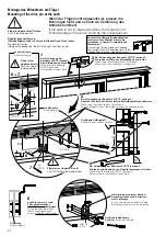
Page 18: ...r durch Lauf und Führungsschiene fixiert ist Set sash into frame and hold in position by two workers until it is fixed by running track and guide track Montage des Flügels nur in Geschlossen Stellung Mounting of sash in position Close only Riegelstelle Locking Montage des Schiebeflügels Mounting of sliding sash Flügel Hubantrieb mechanisch absenken Lower sash lift drive mechanically Beispiel linke...

Page 19: ...acc to position of cap for manual release locking if possible Montage des Bedienteils Mounting of the control keypad nur bei 3 Tasten Bedien teil bei 1 Tasten Bedientaster siehe Anleitung 500905 In case of 3 button control keypad only in case of 1 button control pushbutton refer to instructions 500905 ...

Page 20: ...r Zarge überein stimmen s Abschnitt Möglichkeiten der Kabelführung in case of wiring completely within the frame this hole has to match the position of the corres ponding bore hole in the frame refer to section Possibilities of cable routing Deckelprofil montieren Mount cover profile WICHTIGER HINWEIS Das Deckelprofil muss vor der Montage des Antriebsmoduls mit diesem verschraubt werden Eine nacht...

Page 21: ...ben müssen im Abstand von ca 500 mm in der Armierung befestigt werden Screws have to be fixed every 500 mm within the reinforcement bei Verwendung der Endkappe auf ausreichend Freiraum achten oder vor der Befestigung des Aufbau profils montieren if end cap will be used pay attention to sufficient clearance or mount it prior fastening of the extruded profile Aufbauprofil auf der Seite des Antriebsm...

Page 22: ...ion the holes do not fit and damage of the drive could be the consequence den Mitnehmer mit mind 2 Senkkopfschrauben in der Armierung befestigen Fasten the drive pin with at least 2 countersunk head screws within the reinforcement falls Armierung in diesem Bereich hier bohren senken und Korrosions schutz auftragen in case of reinforcement within this area bore sink and apply corrosion protection M...

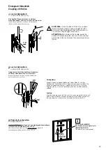
Page 23: ...d element manually mechanical operational force max 150 N max 150 N Einkoppeln Hubantrieb Coupling of lift drive Verriegelung Bringen Sie den Kupplungsbolzen des Hubantriebs A und das Bohrloch der Treibschiene B in Übereinstimmung und schließen Sie mittels Entriegelungsschlüssel Neubautenschlüssel in Richtung Flügel rahmen 6 2 um die Treibschiene und den Antrieb wieder zu kuppeln Locking Bring the...

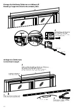
Page 24: ...tte Schiebeflügel Position des Mitnehmers bis Innenkante Antriebsmodul bestimmen Determine measure X from the centerline of sliding sash position of drive pin to inner edge of drive module Außenkante Mitnehmer Outer edge of drive pin Zahnriemen auf Länge L ablängen Cut tooth belt to length L Montage der Abstützung Zahnriemen am Aufbauprofil Mounting of support tooth belt at the extruded profile Ab...

Page 25: ... clamping part at the drive pin WICHTIGER HINWEIS Der Zahnriemen muss wie abgebildet geführt sein IMPORTANT NOTE The tooth belt has to be guided as shown Sicherungsschraube gegen Verdrehen Locking screw against twisting nicht in die Führungs schiene bohren Do not drill into guide rail Zahnriemen an beiden Enden mit jeweils 3 Zähnen im Klemmteil befestigen Fasten the tooth belt at both ends with 3 ...

Page 26: ...tern lock nuts against each other Einstellung der Zahnriemenspannung Adjustment of tension of tooth belt Bei der jährlichen Wartung ist die Zahnriemenspannung zu kontrollieren Ggf ist der Zahnriemen nachzuspannen During annual maintenance the tension of tooth belt must be checked The tooth belt must be retensioned if necessary ...

Page 27: ... 1b 2 2 9 x 9 5 Torx T10 die Abstützteile jeweils mit 1 Schraube am Aufbauprofil befestigen Fasten the supports with 1 screw each at the extruded profile Flügel geöffnet Sash opened Montage der Abstützteile Mounting of the supports ...

Page 28: ...ll be used refer to next page Hubantrieb Lift drive Hubantrieb Lift drive Netzteil Power supply Netzteil Power supply HAUTAU Bus Service Anschluss WLAN Box HAUTAU bus service connection WLAN box HAUTAU Bus Service Anschluss WLAN Box HAUTAU bus service connection WLAN box Bedienteil Bedientaster Control keypad control pushbutton Das Netzteil muss ortsnah montiert werden max Leitungslänge 30 m The p...

Page 29: ...D X6 HAUTAU Bus Service Anschluss Anschluss WLAN Box X6 1 24V X6 2 frei X6 3 HAUTAU Bus X6 4 GND X1 Terminal extension terminal for the connection box X1 1 24 V for ext devices light curtain finger print sensor etc X1 2 test signal for light curtain X1 3 sensor signal of light curtain 2 X1 4 sensor signal of light curtain 1 X1 5 control output for locking control X1 6 ext OPEN control input switch...

Page 30: ...n dass ein unbefugter Eingriff von außen unmöglich ist To be observed The cable has to be laid in such a way that an unauthorized access from outside is impossible Anschluss IR Lichtvorhang Connection of IR Light curtain 1 braun Sender und Empfänger brown emitter and receiver 2 weiß Sender white emitter 3 schwarz Empfänger black receiver 4 blau Sender und Empfänger blue emitter and receiver X1 Pla...

Page 31: ...Netzteil Power supply Netzteil Power supply Bedienteil Control keypad Bedienteil Control keypad Hubantrieb Kontaktübergabe Lift drive contact delivery Netzteil 24 V DC Power supply 24 V DC Netzteil 24 V DC Power supply 24 V DC rot red rot red rot red rot red braun brown braun brown braun brown braun brown schwarz black schwarz black schwarz black schwarz black bei 1 Tasten Bedientaster siehe Anlei...

Page 32: ...delivered condition Refer to installation and operating instructions WLAN Box and Integration of the WLAN Box into a router item codes 500384 and 500623 Platine Antriebsmodul HS S comfort drive Circuit board drive module HS S comfort drive Platine Antriebsmodul HS S comfort drive Circuit board drive module HS S comfort drive Hubantrieb Lift drive Hubantrieb Lift drive HAUTAU Bus HAUTAU bus HAUTAU ...

Page 33: ...Netzteil Power supply Netzteil Power supply Bedienteil Control keypad Bedienteil Control keypad WLAN Box WLAN box WLAN Box WLAN box Schlüsseltaster Key switch oder or Fingerabdruck Sensor Finger print sensor NOT AUS Schalter EMERGENCY STOP switch Hubantrieb Kontaktübergabe Lift drive contact delivery Hubantrieb Kontaktübergabe Lift drive contact delivery Netzteil 24 V DC Power supply 24 V DC Netzt...

Page 34: ... AUS Schalters Brücke X5 1 und 2 entfernen EMERGENCY STOP switch ATTENTION When using an EMERGENCY STOP the bridge X5 1 and 2 has to be removed AUF OPEN braun brown braun brown blau blue blau blue grün green grün green grau grey grau grey rot red rot red rosa pink rosa pink ZU CLOSE IR Lichtvorhang Empfänger Stecker BLAU IR Light curtain receiver plug BLUE IR Lichtvorhang Empfänger Stecker BLAU IR...

Page 35: ...smodul rechts Schiebeflügel von rechts nach links öffnend Example right version drive module on the right sliding sash opening from the right to the left 1 2 3 4 WICHTIGER HINWEIS Nach Umstellungen am S2 Schalter muss das Netzteil mindestens 20 Sekunden vom Strom genommen werden IMPORTANT NOTE After changing the S2 switch the power supply unit must be disconnected from the power supply for at leas...

Page 36: ...s Antriebs bzw der Griff muschel zu vermeiden Stopper nach der Einlernfahrt wieder entfernen IMPORTANT NOTE To avoid damage of the drive or external finger grip position stopper for mechanical limitation width profile related not included within scope of delivery within the area of the fixed sash as shown remove stopper after Teach in run Home Init Beispiel linke Ausführung Schiebeflügel von links...

Page 37: ...l Init Factory reset Full Init Doppelclick Taste ca 30 Sek lang drücken double click press pushbutton for approx 30 sec Signalton an Taster Box Beep at pushbutton box Initialisierung beenden Finishing initialization ca 1 Min warten oder erneuter Doppelclick wait approx 1 min or double click again Schiebeflügel schließt und öffnet automatisch während der Initialisierung Sliding sash closes and open...

Page 38: ...geschlossen ist erkennt das System ob ein Hubantrieb vorhanden ist oder nicht when the sash ist closed the system recognizes whether a lift drive exists or not Hubantrieb vorhanden lift drive exists Flügel senkt sich ab sash lowers Flügel fährt in Richtung ZU bis in die Geschlossenstellung sash runs in direction CLOSE until position CLOSE Initialisierung beendet Der Einklemmschutz sowie alle ander...

Page 39: ...ating mode switch in condition upon delivery 0 bei Ausführung HAUTAU MACO wenn der Betriebsartenschalter auf 3 gestellt wird stoppt der Flügel ca 10 mm vor der mechanischen Endposition in case of version HAUTAU MACO if the operating mode switch will be switched to position 3 during opening the sash stops approx 10 mm before the mechanical end position Diese Einstellung birgt die Gefahr der Fingerq...

Page 40: ...andle Flügel bleibt in Geschlossen Stellung stehen sash remains in position CLOSE Flügel ist betriebsbereit sash is ready for operation Einlernfahrt Home Init Teach in run Home Init sash closes slowly save speed ATTENTION The anti trap protection and all other safety devices are disabled bei 1 Tasten Bedien taster wird die zur Verfügung stehende Taste gedrückt in case of 1 button control pushbutto...

Page 41: ...nen check was successful Lift Slide System has to be labelled according to the EC machine directive Hebe Schiebesystem darf in Betrieb genommen werden The Lift Slide System may be put into operation nein no 1 Einlernfahrt Home Init wurde durchgeführt Flügel ist geöffnet Teach in run Home Init was carried out sash is opened 2 festen Gegenstand z B Werkzeugkoffer am Rahmen angelehnt zwischen Flügel ...

Page 42: ...e at the cover profile only on the non drive side Befestigungswinkel für das Abdeck profil nur 1x auf der Nicht Antriebsseite durch die Durchgangsbohrung Ø 3 2 am Aufbauprofil montieren mount bracket for cover profile only once on the non drive side through the through hole Ø 3 2 at the extruded profile Ansicht von unten view from below L1 Länge Aufbauprofil L1 Length of extruded profile L2 L1 Mon...

Page 43: ... vorher montiert sein In case of retrofitting of the element the element ist already built in the end cap has to be mounted in advance Anschlusskabel durch die Membrantülle fädeln Thread the connecting cable through the membrane grommet Abdeckung mit Schraube M3 x 10 am Antriebsmodul befestigen Fasten cover with screw M3 x 10 at the drive module Montage der Abdeckung des Antriebsmoduls Mounting of...

Page 44: ...eckung für die manuelle Ent Verriegelung nur bei HS comfort drive Mounting of the cover for manual release locking for HS comfort drive only Montage der Abdeckung für den Mitnehmer Mounting of the cover for the drive pin ...

Page 45: ...tton box Fehlerbehebung Fault elimination Wartung Instandhaltung Pflege Wartungscheckliste siehe HAUTAU Dokument 500797 Die Stromzufuhr zum Antrieb muss unter brochen werden wenn Reinigungs oder andere Wartungsarbeiten durchgeführt werden Die Fenster und Antriebe müssen mindestens 1x jährlich auf Unversehrtheit überprüft und gewartet werden Die Antriebe von Verunreinigungen befreien Befestigungs u...

Page 46: ...bauerklärung ja siehe www HAUTAU de hergestellt und geprüft gemäß europäischen Richtlinien Complete system Lift drive and sliding drive HS comfort drive Sash width FB 720 to 3235 mm Sash height FH 1900 to 2800 mm Outer frame width max 6500 mm Max sash weight 330 kg Max sliding force of drive 200 N Electrical characteristics Rated voltage 24 V DC 10 30 Permitted voltage range 21 6 to 31 2 V DC Max ...

Page 47: ...t 330 kg Temperaturbereich 5 bis 60 C Schutzart IP 40 nach DIN EN 60529 im eingebauten Zustand max Zyklenzahl 20 Sliding drive S comfort drive Electrical characteristics Rated voltage 24 V DC 10 30 Permitted voltage range 21 6 to 31 2 V DC Max allowable ripple 20 related to rated voltage Current consumption 4 A at 24 V Switching off in each position blockade yes safety switching off in direction O...

Page 48: ...curtain innen indoor Lichtvorhang Sender und Empfänger Light curtain Emitter and Receiver außen outdoor 2x blau für Empfänger 2x weiß für Sender 2x blue for receiver 2x for emitter Montage IR Lichtvorhang Installation IR Light curtain Teileübersicht Parts overview ...

Page 49: ...g IP 65 Material aluminium Profil colour aluminium anodised Technical data IR Light curtain Lichtvorhang Versorgungsspannung 14 bis 30 V DC Stromaufnahme 60 mA bei 24 V DC Max Einschaltstrom 2 A pro Leiste Welligkeit 10 Ausgang max 120 mA Ansprechzeit 25 bis 100 ms Wellenlänge Infrarot 925 nm Anzahl Sensoren pro Lichtvorhang 16 Anzahl Strahlen pro Sensor 46 Betriebsreichweite 0 8 bis 6 m Max Umgeb...

Page 50: ...Diese Eigenschaften ermöglichen eine hervor ragende Funktionssicherheit Jede Unterbrechung durch ein Objekt oder eine Person im Überwachungsfeld wird detektiert und löst das Schalten des Ausgangssignals aus Between emitter E and receiver R a high density surveillance area is built up with straight and crossed beams A built in calibration feature of each individual beam to eliminate any adjustment ...

Page 51: ...e large optical aperture angle and the automatic calibration feature there is no alignment needed as long as the light curtains are within the specified aperture angle fig 2 For installation of the light curtains please note that the emitter and the receiver profiles are not installed 180 turned to each other that means both cables have to exit the profile in the same direction fig 1 that the prof...

Page 52: ...mt durch α und X bzw β und Y sowie die Elementbreite The range of detection will be defined by α and X or β and Y and the width of the element Der Erfassungsbereich ist so einzustellen dass die gewünschte Funktion sichergestellt wird The range of detection has to be adjusted in such a way that the function will be ensured Empfänger Receiver innen indoor außen outdoor Montage des IR Lichtvorhangs I...

Page 53: ...ieren und die Lichtstrahlen korrespondieren können d die optischen Elemente der Leisten sauber sind und frei von Staub und Schmutz Der Lichtvorhang reagiert auch bis zu einem gewissen Verschmut zungsgrad aber die Leistung ist wesentlich besser wenn die Elemente sauber sind 4 Wenn der Flügel schließt trotz eines Hindernisses gibt es zwei mögliche Ursachen a der Ausgangswählschalter ist nicht richti...

Page 54: ...Test über die BEA Fernbedienung wie folgt auf AN programmiert werden IMPORTANT Before operating the IR presence sensor the automatic test must be programmed to ON using the BEA remote control as follows BEA Fernbedienung BEA remote control Montage IR Anwesenheitsmelder Installation IR Presence sensor Teileübersicht Parts overview Stromversorgung Grün Braun Rosa Grau Rot Blau Gelb Weiß Nicht benutz...

Reviews: