User Interface Options
3–8
Copyright © 2005 Harmonic Inc.
3.4
HRR 4104 Alarms
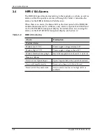
The HRR 4104 provides alarms relating to the module as a whole, as well as
alarms within the specific receivers (A through D). Table 3-2 describes the
alarms for the HRR 4104 Return Path Receiver.
When there is an alarm, the Status LED on the front panel of the HRR 4104
module illuminates red. In addition, every alarm is reported via SNMP and
via the HLP 4200WD front panel display. For information on accessing the
alarms via the HLP 4200WD front panel display, see Section 3.1.
Table 3-2:
HRR 4104 Alarms
Alarm
Description
Module Alarms
Module Low 5 V PS
Power supply voltage is below 4.5 V
Module High 5 V PS
Power supply voltage is above 5.5 V
Module Heat Sink Temp High
Heat sink temperature is above 80° C (176° F)
Receiver Alarms
Receiver Low Optical Input
Optical input is below the optical alarm limit
Receiver Muted Manually
Receiver has been set to Mute: Forced
Receiver AGC Beyond Limits
Gain control is too low or too high (AGC is
enabled)
Summary of Contents for HRR 4104
Page 1: ...HRR 4104 Return Path Receiver Product Manual Manual Part No 700 0051981 Rev A March 2005...
Page 8: ...Overview 1 4 Copyright 2005 Harmonic Inc...
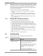
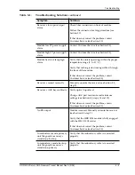
Page 36: ...Maintenance and Troubleshooting 5 6 Copyright 2005 Harmonic Inc...
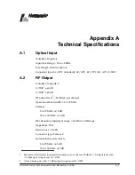
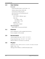
Page 40: ...Technical Specifications A 4 Copyright 2005 Harmonic Inc...
Page 42: ...Harmonic Inc Offices B 2 Copyright 2005 Harmonic Inc...

